Chapter 6: Double-Hull Coastal Types - S, V, W and F Classes
6.1 Introduction
1. As explained in Chapter 5 Admiralty. Officers visited the Italian firm of Fiat San Giorgio Co of Spezia in August 1911 to inspect two 'submersible torpedo boats - the Velella and Medusa - which had been developed and built by that firm from a design by Signor Laurenti for the Italian Government and they were favourably impressed. By 1911 this same type had been adopted by a number of other countries.
2. In 1909 Messrs Scotts of Greenock had acquired from the Fiat Company a licence to construct this type of submarine applicable to all countries under the British flag. In September 1911 Scotts forwarded drawings and specifications of the design to the Admiralty in the hope that Their Lordships would be sufficiently interested to place an order for a trial vessel. They quoted a price of £50,000 for the construction and equipment of a vessel to the same design as those already in commission with the Italian Navy.
3. The tender was accepted and one boat (S1), ordered in December 1911, was subject to the following conditions:
- The firm undertook to execute a formal contract for the boat.
- Separate detailed specifications for hull, machinery and electrical gear would be prepared and submitted for approval.
- The firm carried out all trials of the boat with their own staff under the observation of Admiralty officers, except that the armament trials would be carried out by naval ratings.
- The boat would be built under inspection of Admiralty officers. It was proposed to draw up instructions for inspection of the work on the basis of the firm being granted a free hand to as great an extent as possible consistent with Admiralty views as to safety and efficiency.
4. A figure of £70 000 has been seen for the cost of S1. This was probably a later estimate and is undoubtedly much more reasonable than the original figure. S2 and S3 were ordered in June 1913. The prefix S was apparently adopted to indicate that they were Scotts' built submarines. It is noteworthy that they were the first submarines of any type to be built in Scotland.

S2 under construction at Scott Lithgow's
5. The S Boats were comparable in size with the C Class and both classes carried two bow 18-inch torpedo tubes and four torpedoes. The former were slightly faster both on the surface and submerged. The great difference was of course that the S Boats were double-hulled with the advantage of a very high reserve of buoyancy and ship shape form.
Comparative figures, which bring out this difference in form, are:
| C Class | S Class | |
| Length overall | 142ft 2½in. | 148ft 1½in. |
| Beam maximum | 13ft 7in. | 14ft 5in. |
| Mean draft to underside of flat keel | 11ft 6in. | 9ft 10in. |
| Displacement surface, tons | 290 | 265 |
| Displacement submerged, tons | 320 | 324 |
| Main ballast tanks, tons | 30 | 59 |
| Controlled free flooding space, tons | - | 66 |
| Reserve of buoyancy | 10.4% | 47% |
A General Arrangement of S1 is shown in Plate 16 and an Outline Elevation in Fig 6.1.
6.2 Design
6. This was a typical Laurenti design of the partial double-hull type. The outer hull was of ship shape form with the maximum beam near the top, which formed a wide walking deck parallel to the pressure hull throughout the length of the boat. The double-hull portion started about 56 feet from the bows and extended aft for about 45 feet in way of the control room and engine and motor rooms. The sections of the pressure hull were all far from circular and there were discontinuities in the hull. The latter is better seen in Fig 6.1
The after end was of a ducktail form, which gave good submersion for the twin propellers. The bow was fine and cut up for a depth of about 2ft from the keel line and back for a distance of 10ft where the lips of the torpedo tubes were sited at keel level in a form of bulbous bow.
Baling flats were fitted in the double-hull about LWL level. The double-hull below these flats contained main ballast and oil fuel tanks. The portion above the flats was controlled free flooding space and this space extended some distance forward and aft of the doubler-hull. However, some of the superstructure space at the forward and after ends was free flooding but not controlled.
6.2.1 Dimensions
7. The Loa was 148ft 1½in and the Lph about 138ft 3½in. No reasonable figure has been seen for Lbp but it was of the order of 137ft.
The maximum beam given during building was 13ft 9½in but this was the maximum beam at the surface waterline.
The maximum beam of the hull was much nearer the deck and is given by Scotts as 14ft 5in.
The beam of the pressure hull amidships and throughout the machinery spaces was approximately 10ft with a sudden decrease to 9ft in the control room.
The maximum overall depth of the outer hull was 12ft 3in in the control room and of the inner hull 6ft 7in in the engine room and control room increased to 6ft 11in in the motor rooms. A false floor was fitted in the control room to give a working height of 6ft 4in. There were no internal frames in these spaces.

Fig 6.1
8. Scotts give the draught fully loaded as 10ft 4½in and DNC as 9ft 10in. The difference is probably due to the ballast keel and the former is taken as correct to the underside of ballast keel. This gives a freeboard to the main deck of 2ft 5in and to top of conning tower about 6ft 9in.
6.2.2 Displacement and Stability
9. When the displacement sheet was prepared the total submerged capacity was 382.3 tons including 66 tons of controlled free flooding space. During building, DNC gave the submerged displacement as 386 tons and a surface displacement of 253 tons a difference of 133 tons and stated they carried 120 tons of main ballast water. Scotts on completion gave a submerged displacement of 390 tons 'with the superstructure empty' this undoubtedly means ordinary free flooding spaces and surface displacement of 265 tons, a difference of 125 tons. These figures are in reasonable agreement taking into account changes over the building period.
10. The differences between the surface and submerged conditions include main ballast water and the capacity of the controlled free flooding spaces. To meet the standards laid down in Chapter 2, the latter is not included in the submerged displacement but is included in the calculation of reserve of buoyancy. It is reasonable to accept the figure of 66 tons for controlled free flooding water leaving 59 tons of main ballast water. The Laurenti standard was that the percentage of main ballast to surface displacement should be not less than 20%. The above figures give 22%.
Figures taken as reasonable are submerged displacement 324 tons, surface displacement 265 tons and reserve of buoyancy 47%.
The only figures available for stability were given by DNC in the design stage as GM 22.4in and BG 8.5in and later a BG of 6.9in.
6.3 Speed and Endurance
11. The builders quoted the following figures, seemingly after trials:
- Speed surface - 13.25 knots at 650 bhp
- Speed submerged - 8. 5 knots
- Endurance surface, miles - 1600 at 8.5 knots
- Endurance submerged, miles - 75 at 5 knots
Reference (a) above, the design speed was 13 knots at 600 hp and CB 1815 (1914) gives the same figures. The service speed is taken as 13 knots. A statement has been seen to the effect that 15 knots was obtained on trials but this is discounted although it suggests that the design speed was obtained and probably slightly exceeded.
Reference (b) above, the design speed quoted by Scotts and DNC was 8.5 knots. Again, it has been stated that 9.7 knots was obtained on trials, but this is discounted as normal although it indicates that 8.5 knots was a realistic speed, especially in comparison with the C Class of comparable size but less power. It is of interest that whereas Scotts give the motor power as 400 bhp, DNC quoted 534 bhp, probably with overload, which might account for the high trial speed mentioned.
Reference (c) above, this surface endurance is confirmed by all authorities. A figure of 690 miles at full speed is also quoted and is reasonable with a fuel consumption figure of about 0.5lb per bhp hour and 8 tons of fuel.
Reference (d) above, this is probably a design figure and no other figures are available. The full speed of 8.5 knots could be held for one hour.
6.3.1 Structure
12. The S Class was the first foreign designed partial double-hull type built in this country and unfortunately few details of the construction are available.
In way of the double-hull amidships there were no internal frames, but angle bar frames on the outside of the pressure hull were stayed to angles on the outer hull together with a reasonable number of divisional bulkheads. Forward and aft very deep plate frames were fitted inboard in the pressure hull. The frame spacing was mainly of the order of 2ft but it varied greatly throughout the length of the hull.
13. Ten intermediate WT bulkheads subdivided the hull, if anything the sub division was excessive. An interesting point is that the aftermost compartment, the rudder compartment, had dished bulkheads requiring no stiffeners and this applied also to the after bulkhead of the starboard motor room and the forward bulkhead of the control room. This practice of curvature extended to a heavy camber on tank tops, to the end bulkheads of the tanks in the double-hull and even to a very heavy upward curve of the pressure hull in the machinery spaces. All this may have been good practice at some cost but unfortunately there were a number of discontinuities in the pressure hull with a consequent loss of strength.
14. Drawings and information about the S Class are extremely scarce since practically all of the records at Scotts were destroyed by enemy action in 1941. However, a plan of the Pumping, Flooding and Trimming Arrangements has been found and the following statement on the layout of compartment and tanks etc has been prepared from it, as has Fig 6.1
The compartments and tanks between main bulkheads starting from forward were:
- Fore end free flooding space.
- Forward trimming tank.
- Buoyancy tank. (Also called an air tank).
Torpedo compensating tank.
Buoyancy tank (Air tank)
The two torpedo tubes passed through these tanks. Spare torpedo compensating tanks, sided port and starboard, over the above tanks with an access space between and a stowage tank over the torpedo tubes for carrying the spare torpedoes.
- Torpedo Room with a small reserve oil fuel tank at the forward end.
- Probably officers' accommodation and forward battery.
- Control Room with Nos 1 & 2 main tanks in double-hull.
- Engine Room with oil fuel tank and compensating tank in double-hull.
- Port Motor Room with No 3 main tank in double-hull.
- Starboard Motor Room with No 4 main tank in double-hull.
- Probably crew accommodation and after battery.
- Ditto.
- Probably hydroplane gear and auxiliary machinery.
- Rudder compartment.
- After trimming tank.
- Free flooding space.
6.4 Tanks
6.4.1 Main Ballast Tanks
15. Four main ballast tanks were sited in the double-hull portion amidships together with an oil fuel tank and compensating water tank. There were no internal main ballast tanks.
As in all Laurenti designs, baling flats were fitted in the externals just above the LWL and the tanks extended below these flats from port to starboard Sides. Each main tank was flooded through two 8in Kingstons, port and starboard of the ML at the keel. Two 3in suction pipes from the main line were also fitted to each main tank. Tank capacities are not available but the actual amount assumed is 59 tons; see Para 10.
The spaces above the baling flats and also part of the superstructure forward and aft of the double-hull were of watertight construction. They were undoubtedly fitted with Kingstons or scoops for flooding and vents, as was the normal practice in this type of hull. They were therefore controlled free flooding spaces. The capacity has been assumed as 66 tons. The vents to all of these tanks and spaces were operated by hand.
Two buoyancy tanks, also called air tanks, were fitted forward around the torpedo tubes inside the pressure hull. They could not have been connected in any way with the buoyancy or submerged displacement. They must have been firing tanks.
6.4.2 Oil Fuel Tanks
16. One tank was in the double-hull amidships and a reserve oil fuel tank, forward near the rear doors of the torpedo tubes. The total capacity of fuel carried is stated to have been 8 tons. This is the first time that oil fuel is carried in external tanks.
A compensated oil fuel system was fitted by means of which sea water was automatically admitted to the fuel tanks to replace the oil being used by the engines. This practice had started in E1. Further details are given in Chapter 25.
6.4.3 Other Tanks
17. A compensating tank amidships in the externals had a capacity of not more than 2 tons. It was fitted with one 8in Kingston and one 3in suction. This with the two trimming tanks must have been used to compensate for all changes in weight and in water density other than for the torpedoes. A statical diving tank was not fitted.
6.4.4 Main machinery
18. Two sets of Scott-Fiat two-cycle six cylinder diesels were installed each developing 325 bhp at 460 rev/min. They differed from the diesels used in previously built RN submarines being of reversible two-cycle type capable of using any kind of fuel oil. Further details are given in Chapter 25 There is some doubt whether the full 650 bhp was maintained in service.
Two main motors developed 400 bhp as stated by Scotts. CB 1815 (1914), gives 300 bhp, whilst DNC mentioned 534 bhp which suggests that the motors could be overloaded as they could be in the C Class. The port and starboard motors were in separate motor rooms.
The battery consisted of 240 cells in two sections, one forward of the control room and the other aft of the motor rooms.
This same arrangement was adopted in E9-11, which were laid down a couple of months before S1.
6.5 Armament
19. The forefoot was cut up and back for 10ft. The two 18-inch bow tubes were fitted very low in the vessel and angled bow down so that the centres of the lip ends of the tubes were less than 1 foot from the underside of keel. The tubes at the fore end formed a sort of bulbous bow structure at keel level. Four torpedoes were carried, the two spares being in stowage tank over the torpedo tubes. The bow caps opened outwards to port and starboard. A gun was not carried.
6.6 Other Equipment
20. Safety appliances were introduced for the first time in British submarines, although they were a normal feature in Laurenti type submarines. The S Class was fitted with lifting buoys, a telephone buoy and divers air connections.
21. Further details of the main machinery and armament and of other equipment are given in Chapters 20-32. They include a number of interesting items new to British submarines such as:
- Forward and after housing hydroplanes which however were not very satisfactory in service.
- Quick opening and closing rear doors to torpedo tubes, with interlocking gear to the bow caps.
- New style torpedo-loading hatch.
- Safety appliances.
6.7 Operational Features
22. S1 was completed in August 1914 and S2 and 3 in May and September 1915. They were sold to the Italian Government soon after that country entered the war in 1915. S2 and S3 were transferred about September 1915 and S1 in July 1915. These three boats therefore had little service with the RN.
23. Lipscombe states that 'the S Class were not a great success because they were unsuitable for the peculiarities of the North Sea weather and its high short seas conditions which the Italians did not find in the Mediterranean'. One is inclined to doubt whether a boat with such a high reserve of buoyancy was any worse in the North Sea than the then existing RN submarines of equivalent size. However, it is known that they were not very popular with RN submarine officers. One of the main reasons for this may have been that on passage to Portsmouth after delivery in 1914, S1 experienced difficulties with her housing hydroplanes. Although various remedies were tried to overcome the troubles hydroplane defects were a constant source of concern. Another point was undoubtedly the much greater time to dive from that in contemporary RN submarines.
6.8 V Class
24. The V design was Messrs Vickers' interpretation of a Coastal type submarine to the requirements laid down by the 1912 Submarine Committee given in Chapter 5. The firm in some ways followed the Fiat S design building at Scotts in that it was based on the Laurenti partial double-hull principle.
25. V1 was in the 1912/13 Programme and was ordered from Vickers on 23 March 1913. This would appear to have been a formality since the vessel was laid down in November 1912. V2-4 in the 1913/14 Programme were ordered in August 1913. Changes were made from V1 in the principal dimensions of the hull for V2-4 although the layout remained generally the same. The estimated cost was £76 100 later revised in an amended tender to £75 779.
26. The main characteristics of the V Class compared with the S Class and C Class are as follows:
| V2-4 | S Class | C19-38 | |
| Length overall | 147ft 6in. | 148ft 1½in. | 142ft 2½in. |
| Displacement surface, tons | 391 | 265 | 290 |
| Displacement submerged, tons | 457 | 324 | 320 |
| Speed surface, knots | 14 | 13 | 13 |
| Speed submerged, knots | 9 | 8.5 | 8 |
| Torpedo tubes, bow | Two 18-inch | Two 18-inch | Two 18-inch |
The figures given above are for V2-4; the dimensions of V1 differed slightly. The length of V1 was 144ft 0in and for the later vessels, two extra 21in frame spaces were added to the battery tank compartment and to the torpedo tube compartment, whilst the foremost tank compartment in the bows was shortened by 3ft 6in. Giving an increase in overall length of 3ft 6in in V1, the pressure hull in the double-hull portion was far from fair. In V2-4 this part of the hull was made fair and in doing so the beam and depth of the pressure hull and outer hull were changed.
27. Drawings of the class are shown in the following plates:
- Plate 17: V1 - General Arrangement
- Plate 18: V2 - General Arrangement
- Plate 19: V Class - Construction Sections
These drawings may possibly be design drawings from which the building drawings were developed. The reason for assuming this is because some of the main tanks shown were used for other purposes before the boats were completed.
6.9 Design
28. Although called a double-hull the design was actually of partial double-hull on the Fiat-Laurenti principle, the double-hull being limited to the middle portion of the boat with the outer hull fairing into the pressure hull at the forward and after ends. Although the V Class and S Class were approximately the same overall length, Vickers applied the double-hull principle over a length of 75ft as against 45ft in the S Class. Furthermore they eliminated discontinuities in the pressure hull within the double-hull in V2-4 except of course at the ends, which was an important advance. This was a refinement on V1 as shown in comparing Plate 17 and Plate 18 which however itself was better than the S Class in so far as strength was concerned.
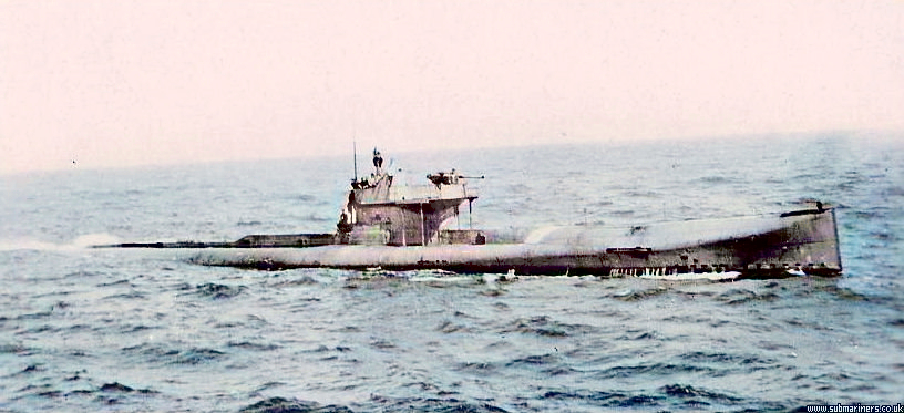
V1 at sea
The outer hull was ship shape and the sections of the pressure hull far from circular, see Plate 19. The bow was fine and the forefoot sharply cut up to enable the torpedo tubes to discharge under the fore end. The stern was also fine but dropped to allow good submersion of the propellers. Vickers carried out a series of tank experiments on several forms of hull before choosing the one for this class.
6.10 Dimensions
29. The length overall given by the builders was 144ft 0in for V1 and 147ft 6in for V2-4. They gave the same figures for Lbp but the actual figures for Lbp were 139ft 10in for V1 and 143ft 4in for V2-4. The figures for Lph were the same as the Loa since the fore end tank was tested to 50lb/in2.
The builders gave the moulded beam and depth of the pressure hull amidships in V1 as 12ft 6in and 10ft 6⅛in and in V2-4 as 12ft 9in and 10ft 7in respectively. Because of the method of working the plating and external framing of the pressure hull the figures for maximum beam and depth of the pressure hull were the same as the moulded figures. The maximum beam to outside of external plating and the maximum depth ex ballast keel are given for V1 as 16ft 6in and 13ft 4in and for V2-4 as 16ft 3in and 13ft 4in respectively.
The ballast keel was 6in deep and the bottom of the drop keel 8in below the flat keel.
The mean surface draught at 386 tons displacement is given as 11ft 6in in V1 and 11ft 4½in in V2-4. At the true displacement of 391 tons in the latter the draught would be approximately 11ft 6in.
6.11 Displacement and Stability
30. The figures for submerged displacement given by both Vickers and DNC varied over the years from 453 to 500 tons. The main reason for these differences was that in some cases the capacity of the controlled free flooding spaces was included. There were also changes between the design and as built capacities of main ballast tanks.
From the hydrostatic calculations for V1, the buoyancy of the submerged hull was 480 tons below the datum line, and allowing about 6 tons for appendages gives a total of 486 tons, but it includes the capacity of the free flooding spaces below the datum of 33 tons. The submerged displacement is therefore 453 tons. These figures are quoted by both Vickers and DNC at various times but the latter is the correct one. There was 7.7 tons of free flooding space above the datum.
As designed, V1 had seven external main ballast tanks of 58 tons capacity and four internal main tanks of 30.75 tons. This gives a total of approximately 89 tons of main ballast a figure used in the design to give a surface displacement of 364 tons. However during building two of the internal tanks were converted into stowages for air bottles.
Furthermore No 1 main tank in the bows was also converted into a buoyancy tank and later on Vickers did not include the capacity of this tank in the total of main ballast water. It can only be surmised that the tank was of necessity kept empty because of trim submerged. These changes reduced the internal main ballast to 8.8 tons.
Figures for V1 were therefore external main ballast 58 tons, internal main ballast 8.8 tons and controlled free flooding space 40.7 tons with 33 tons below and 7.7 tons above the datum line. With a submerged displacement of 453 tons, the surface displacement was 386 tons and the reserve of buoyancy 27.9%.
31. The same circumstances applied to V2-4. The calculated buoyancy of the submerged hull plus appendages was about 494 tons including 37 tons of free flooding space. There was 8.5 tons of controlled free flooding space above the datum line. The submerged displacement was therefore 457 tons.
As designed the number of main ballast tanks was the same as in V1 with a capacity of 57.5 tons in external tanks and 27.4 tons in internal tanks. As in V1 the main tank in the bows was converted into a buoyancy tank, a forward internal main tank into an air bottle stowage and an after main tank into a compensating tank. This reduced the internal tank capacity to 8.2 tons. The total main ballast water available was therefore about 66 tons.
Figures for V2-4 are submerged displacement 457 tons, surface displacement 391 tons and reserve of buoyancy 28.5%.
32. It is interesting to note that although the great merit of the double-hulled boat was claimed to be the large reserve of buoyancy, the value obtained in this class was not that much greater than the 25.3% achieved in D3-8 with saddle tanks.
33. Vickers quoted the surface GM and submerged BG at one stage as 19-19.5in and 8.25in respectively and another time as 16in and 7in respectively. DNC in 1912 gave the latter figures, which are therefore design figures. Although no actual inclining experiment results have been seen the first figures quoted above, i.e. GM 19-19.5in and BG 8.25in are probably later figures obtained as a result of inclining.
6.12 Speed and Endurance
34. The maximum speeds given consistently by Vickers and DNC are 14 knots surface and 9 knots submerged. There is some doubt however whether these speeds were actually obtained and 13 knots and 8.5 knots respectively have been mentioned. It is also understood that the latter were the figures mentioned by Vickers when first submitting the design. On the 900 hp of the main engines in the V Class 14 knots can be expected in comparison with the other classes mentioned in Paragraph 26. With a submerged bhp of only 300 hp in V1 and 380 hp in V2-4 the submerged figure of 8.5 knots is more reasonable than 9 knots at least for V1. However with overload 470 bhp could be developed in V1 and 570 bhp in V2-4 and under these conditions an excess of 9 knots would be achieved.
35. In the design stage Vickers gave the surface endurance for both V1 and V2-4 as 1200 miles at 14 knots, 2000 miles at 12 knots and 3000 miles at 9 knots. DNC also quoted the figure of 2000 miles at 12 knots. The figures mentioned are accepted for V1 but V2-4 carried 6% less fuel and the endurance figures should be decreased proportionately.
The submerged endurance has been given as 74 miles at 5 knots and 85 miles at economical speed. These figures are higher than for similar size boats of the time and with only 132 cells as against 166 and 240 cells in the C Class and S Class respectively are considered optimistic. The battery discharge rating was less than one hour at full speed. Reasonable figures for speed and endurance are given in Appendix IIIA.
6.13 Structure
36. Plate 19 shows details of the construction in way of the double-hull and the sections forward and aft of the double-hull. Points of Interest are:
- The pressure hull throughout is of 15lb special steel plating worked in raised and sunken strakes except that the keel strake outside the double-hull is 20lb decreasing to 17lb at the ends.
- The outer hull in the double-hull portion is of 10lb plating in main tanks, 15lb plating in way of fuel and auxiliary ballast tanks, a 20lb keel strake and 8lb plating in way of the controlled free flooding space.
- The WT baling flats - No 2 longitudinals - in the double-hull are only about 2ft below the top of the hull amidships and about 6in above the normal surface waterline.
- No 1 longitudinal is continuous throughout the double-hull at the maximum beam and is of 10lb plating non-WT in the main tanks and 15lb plating WT or OT where it forms the tops of the auxiliary ballast and oil fuel tanks.
- In way of the double-hull all frames are in the form of lightened plate frames between the inner and outer hulls spaced 21in apart. The angles connecting the frames to the hull plating were joggled so that no filling pieces werenecessary. There are no frames within the pressure hull.
- Frame spacing was generally 21in. Decreasing to 18in at the extreme forward end. The frames forward and aft of the double-hull were to be 4in x 3in x 3in x 11.89lb channels except that up to the foremost and aftermost WT bulkheads alternate frames were 9in deep built-up frames of 10lb plate with 5lb angle bars. It is understood however that instead of the channels, 11.53lb Zed bars were used in V1 as then being used in the E Class, and 4in x 4in x 11.25lb angle bars in V2-4.
37. Although the pressure hull sections were far from circular and the plating was only 15lb as against 20lb in the
C Class with circular sections the strength of the double hull lay in the framing. The V Class was designed for 150 feet diving depth as against 100 feet in the C Class. However, this was at the expense of weight. Some figures given by Vickers bring out this point:
| Surface Displacement | Hull Weight | Percentage | |
| (a) tons | (b) tons | (b) / (a) | |
| C1 | 287 | 118 | 41% |
| D1 | 483 | 201 | 41.6% |
| V Class | 391 | 183 | 47% |
38. Internal main WT bulkheads were fitted each end of the double-hull portion of the boat and this middle compartment tested to an internal pressure of 35lb/in2. Two Intermediate bulkheads were in this amidships space but they were not as strong as the main WT bulkheads being tested to 15lb/in2 only. The remainder of the pressure hull was tested to 30lb/in2 instead of 35lb/in2 in the D Class. Another main bulkhead was fitted to enclose an after main hull compartment containing the hydroplane and steering gears and was fitted with a WT door for access. These boats therefore can at a stretch be called six compartment vessels.
39. A superstructure of 5lb plating about 4ft 6in wide and 2ft high extended above the outer hull from the bow to some way abaft the bridge and enclosed the topside fittings. Even the bridge was streamlined within this width so that throughout most of the length of the boat the top of the double hull formed a large reasonably flat recreation deck. About 40ft of the superstructure amidships was watertight and made common with the controlled free flooding space of the double-hull. The outer hull abreast the superstructure both port and starboard sides were made portable presumably for access to and maintenance of the externals.
40. The ballast keel extended for nearly 80% of the length of the boat from the foremost WT bulkhead to the stern fin and was generally 6in deep. As built it weighed 17 tons in V1 and 22.5 tons in V2-4. A 5-ton drop weight was fitted amidships, 8in deep, so that the bottom of the drop keel was 2in below the underside of the ballast keel. Nine-inch bilge keels were fitted and with the ship shape form were undoubtedly necessary.
6.14 Tanks
41. The tests applied to the various tanks were more or less standardised for the E Class by the time the V Class were building as given in Chapter 4, Paragraph 64.
Differences in V1-4 from those standards are as follows:
- The main compartment in way of the double-hull was tested to 35lb/in2 as was the conning tower. The sub-divisional bulkheads within this main compartment were tested to 15lb/in2 only. The remaining pressure hull main compartments were tested to 30lb/in2 only.
- The chain locker was tested to 50lb/in2.
- Battery tank to 1lb/in2.
- External main ballast tanks to 15lb/in2
- The controlled free flooding space was tested to 2ft head above the datum line.
Arrangements of tanks and compartments are shown for V1 in Fig 6.2 and for V2-4 in Fig 6.3.
6.14.1 Main Ballast Tanks
42. There were seven main ballast tanks in the double-hull, Nos 3, 4, 5, 8 and 9 each extending round the hull below the port and starboard baling flat, and two sided tanks Nos 6 and 7 above oil fuel tanks. Each tank was flooded through one Kingston hand operated from a position high up in the boat. The Kingstons were themselves high up in the tanks and flooding trunks fitted from the Kingstons to the bottom of the tanks. The flooding time must therefore have been slow.
Originally, three internal main ballast tanks were to be fitted, as shown in Plate 17 and Plate 18. However, before the boats completed, the foremost one in the torpedo room was converted to an air bottle stowage and one aft in the crew space to an air bottle stowage in V1 and a compensating tank in V2-4. This left No 2 main tank internally and decreased the capacity of the internal ballast water by approximately 14 tons.
No 1 main ballast tank in the fore end was also an internal tank tested to 50lb/in2, although originally fitted with a Kingston it was eventually termed a buoyancy tank and was not used for main ballast water.
The total capacities of the external tanks was 58 tons in V1 and 57.5 tons in V2-4 and of the internal tank 8.8 tons in V1 and 8.2 tons in V2-4. The capacity of No 1 main tank (made a buoyancy tank) was 8.89 tons in V1 and 5.27 tons in V2-4.

Fig 6.2

Fig 6.3
43. The controlled free flooding space occupied the space above the baling flats throughout the length of the double-hull and also the amidship portion of the superstructure. The capacity of this space was 40.7 tons in V1 and 55 tons in V2-4 and was in no way WT subdivided. It was not fitted with Kingstons or flooding valves.
The number of vents fitted is not known but must have been reasonably large in a space of this size to prevent too much of a hold up in diving.
6.14.2 Auxiliary Ballast & Compensating Tanks
44. V1 had four auxiliary ballast tanks with a total capacity of 4.4 tons sited amidships in the lower half of the outer-hull. They were sided about the vertical keel. Two compensating tanks forward of 0.97 tons capacity each were undoubtedly for torpedo compensating i.e. WRT tanks.
V2-4 had similar arrangements except that the auxiliary ballast capacity was increased to 6 tons and a compensating tank of 8.8 tons capacity fitted aft. As explained in Paragraph 31 this tank was originally an internal main ballast tank and its adoption for compensating water instead of the stowage of air bottles as in V1 may have been a necessity to add water aft to obtain a trim submerged. The oil fuel was self-compensating and there was no need for compensating water as such of this amount.
6.14.3 Oil Fuel Tanks
45. Oil fuel was carried in three external tanks in way of the engine room, 17.25 tons in V1 and 16.25 tons in V2-4 and was self-compensating. These tanks extended to about half way up the external hull. The lubricating oil tanks and drain tank were also in the externals.
6.14.4 Other Tanks
46. V1 was running parallel to E12-16 during building and the tanks fitted were similar in most respects. The only differences of note are that.
- Separate -compartments we re allocated as air bottle stowages and were fitted with portable plates for shipping the bottles, and
- Built in firing tanks were deleted and a cylindrical firing tank fitted in the torpedo compartment reverting in fact to the arrangement in the HOLLAND boats. Very soon the policy of fitting separate firing columns was to be introduced.
6.15 Main Machinery
47. Two sets of Vickers four-cycle eight cylinder vertical SA diesels each one developing 450 bhp at 450 rev/min. They were the first Vickers submarine engines to have steel cylinder jackets, which had previously been of cast iron.
Two single armature main motors built by Laurence Scott for V1 developed 150 bhp each and those for V2-4 built by Don Works developed 190 bhp each. The motors could be overloaded to give 235 bhp each in V1 and 285 bhp each in V2-4.
The battery consisted of 132 Exide cells divided into two sections of 66 cells each with a working voltage of 130 volts in parallel and 260 volts in series. All the cells were in one battery tank. The number of cells carried was small for this size of boat when it is considered that the C Class had 166 cells and the A Class of less than half the displacement carried 120 cells. However, the designed submerged speed was obtained but the endurance suffered.
6.16 Armament
48. Two 18-inch bow tubes were low in the vessel forward as shown in Plate 18. Four torpedoes in all were carried. It is stated that a 12-Pounder gun was fitted, presumably after completion.
49. Further details of main machinery and armament and of other equipment are given in Chapters 20-32.
6.17 W Class
50. The visit of a team of Admiralty officers to Italy and France in 1911 to inspect foreign submarine designs is mentioned in Chapter 5. At the Fiat Co of Spezia the Laurenti designed partial double-hull vessels had favourably impressed the inspecting officers. At the Schneider Yard at Creusot, Toulon the team inspected some French submarines to M Laubeuf's design. It is understood that the submarines they saw were based on the French Pluvoise Class as modified by their designer Laubeuf on his subsequent association with Messrs Schneider Et Cie. They were called Schneider Laubeuf type submersibles.
51. Although the inspecting officers found the French boats interesting they recommended that this type should not be built for the RN. They considered that they were too long and too slow and they did not like the external torpedoes in frames. But there must have been other reasons as well because although the French boats were slightly longer than the Italian boats which they did recommend, the speed and the internal torpedo armament were the same. However, they were overruled and two submarines of the type were ordered from Messrs Armstrong Whitworth & Co on 14 January 1913. The two vessels, W1 and W2, were the first submarines to be built by Armstrong Whitworth.
52. In August 1913 a further order was given to the firm for two more boats, W3 and W4, of somewhat similar type. It is understood that, although in the opinion of submarine officers, the W type compared unfavourably with contemporary coastal designs. It was necessary to order W3 and W4 since an agreement had been made with Armstrong Whitworth when ordering W1 and W2 that the firm would be given orders for two submarines a year to the number of six. However, the next year, the firm started to build E boats under the War Emergency orders in November 1914 and no further orders for W boats were placed. W3 and W4 were redesigns of W1 and W2 made by Laubeuf himself to meet RN requirements based on our knowledge of the W1 and W2 design.
53. The four boats saw little service with the RN and little detailed information about them can be found. W1 and W2 were repeats of an actual type and some particulars were given by DNC in 1913 but at that time only a few dimensions were known for W3 and W4. W1 and W2 were ordered in January 1913 but they were not laid down until October and December 1913. Although working drawings would have been available they would have to be redrawn to British standards. However, when they got started, the vessels completed in January and May 1915 in very good building times of 15 and 17 months. Considerable major changes were made in W3 and W4, which were completed in February and June 1916. All four vessels were sold to the Italian Government in June/July 1916.
6.18
54. The following particulars of W1 and W2 were given by DNC some time in 1913 and were probably supplied by Messrs Schneider:
| Length overall | 171ft 11in. |
| Beam maximum | 15ft 4¼in. |
| Displacement surface | 331 tons |
| Displacement submerged | 499 tons |
| Speed surface | 13 knots |
| Speed submerged | 8.5 knots |
| Torpedo tubes, bow | Two 18-inch |
| Torpedo tubes, external | Four 18-inch |
| No of torpedoes | 8 |
A General Arrangement is shown in Plate 20.
The estimated cost of W1 and W2 was £84 500 and of W3 and W4 £78 500 the difference being mainly due to the deletion of the external torpedoes.

Fig 6.4
55. They were complete double-hulled boats of the Laubeuf type with the pressure hull completely surrounded by an outer hull, the double-hull being used as main ballast tanks. There were no baling flats or controlled free flooding spaces. The pressure hull was slightly elliptical amidships becoming more so forward and aft. The dimensions of the pressure hull were the smallest ever in British submarines. Being 2ft 6in and 3ft 6in less respectively in beam and depth than in the C Class of less displacement and less than in the Holland Class. This was offset to some extent by the fact that there were no internal frames. The outer hull was ship shape.
6.19 Dimensions
56. The figures given must be taken as approximate except where shown in Paragraph 54.
In W1 and W2 the Loa was 171ft 11in and the maximum beam near the top of the outer hull 15ft 4¼in. The maximum beam of pressure hull amidships was 11ft and maximum depth 10ft. The overall depth of the outer hull was 10ft 6in and the ballast keel about 21in deep.
The draught at 331 tons displacement was 8ft 10½in with a freeboard to the superstructure of 5ft 10in and to the bridge 9ft 1in.
57. In W3 and W4 the Loa was decreased to 149ft 11in and the overall beam increased to 17ft 10in. There was about 10 tons decrease in both submerged and surface displacements whilst the capacity of the outer hull remained the same. The Internal dimensions of the pressure hull must have increased in beam and possibly depth. This would have been an advantageous change. The draught increased to 9ft 4in.
6.20 Displacement and Stability
58. In W1 and W2 the submerged displacement was 499 tons with 168 tons of main ballast tank capacity in the externals. The surface displacement was 331 tons with reserve of buoyancy 50.8%.
The stability given was GM 27in and BG 7.25in for W1 and W2.
In W3 and W4 as designed the displacements were submerged 490 tons and surface 320 tons. These figures give a reserve of buoyancy of 52.8%.
6.21 Speed and Endurance
59. The maximum surface speed was 13 knots at 710 bhp in W1 and W2. The hp in W3 and W4 appears to have been increased to 760 bhp; in spite of the change in form 13 knots should have been achieved in the class.
The surface endurance is given as 1600 miles at 10 knots using both engines and 2500 miles at 9 knots on one engine. These figures are coupled with 12.9 tons of oil fuel. There was apparently stowage for 18 tons of fuel in W1 and W2 and 13.6 tons in W3 and W4. Exact endurance figures are therefore uncertain.
60. The submerged speed was 8.5 knots at 480 bhp. This seems to be pessimistic compared with the S Class, V Class and F Class although much depends on the topside fittings for example the external torpedo tubes.
The submerged endurance is given as 68 miles at 5 knots.
6.22 Structure
61. Amidships the pressure hull plating was keel 19lb, garboard strakes 16lb and else where 14½1b. With a small near circular hull with external plate frames this was a strong hull. Normally we had used nothing less than 17½lb except that 15lb had been used in the V Class.
The outer hull had a 22lb keel, 14½lb garboard strakes then, 7 7½lb plating below the waterline and 6½lb above. The smaller thicknesses did not allow much of a margin for wastage or damage. In Admiralty designs 10lb was the normal thickness.
6.23 Main Machinery
62. All four boats were fitted with two Schneider Laubeuf type diesels with eight cylinders giving a total of 710 bhp at 400 rev/min in W1 and W2 and with six cylinders giving a total of 760 bhp in W3 and W4.
The two motors developed 480 bhp and the battery consisted of 220 cells of the Fulsen or Tudor Type.
6.24 Armament
63. All four boats had two 18-inch bow tubes and carried two spare torpedoes. W1 and W2 had, in addition, four 18-inch external tubes actually called 'frames' which were undoubtedly the French pattern of carriers from which when fired the torpedo was simply detached from the frame and then proceeded under its own power. No spare torpedoes were carried. These frames were not fitted in W3 and W4.
6.25 Operational Features
64. Reference (11) states that 'they were not really satisfactory. The conning towers were too low and they did not have the sea keeping qualities we needed here'. The freeboard to the bridge was about 3ft less than had been decided upon in D Class and E Class at that time, but the W Class had a large reserve of buoyancy and the freeboard to the superstructure deck was as good as contemporary RN boats. There is no doubt however that they were not popular with RN submarine officers probably because the space available inside the pressure hull was marginally less than in the C Class and this must have affected habitability.
In extenuation of any adverse criticism of the W Class, Sir Philip Watts states they 'had unusually excellent control when diving and technical excellence and practical efficiency of all detailed design in connection with their flooding, venting, electrical and subsidiary installations'.
6.26 F Class
65. By the end of 1912 S1 and V1 were building and early in 1913 W1 and W2 were ordered. The first two were of partial double-hull construction and the latter of wholly double-hull construction. These three types of 'experimental' vessels all undoubtedly had Individual features of merit. In 1913 the Admiralty decided to produce a standard Admiralty Coastal submarine design with double-hull features. This design became the F Class.
6.27 Design
66. The main features were as designed:
| Length overall | 151ft 0in. |
| Beam maximum | 16ft 0-5/8in. |
| Displacement surface | 353 tons |
| Displacement submerged | 525 tons See Paragraph 70 |
| Speed surface | 14.5 knots |
| Speed submerged | 8.75 knots |
| Torpedo tubes, bow | Two 18-inch |
| Torpedo tubes, stem | One 18-inch |
A General Arrangement drawing of F1 is shown in Plate 21.
The lead boat F1 was ordered from Chatham Dockyard in the 1913/14 programme and was laid down in December 1913. In the 1914/15 programme, two further boats were ordered F2 at J S White at Cowes and F3 at J I Thornycroft at Southampton.
An early estimated cost to given as £66 000, but additional figures of both £60 000 and £80 000 have been seen. About the same time the cost of the V Class was being given as about £76 900 so that the figure of £80 000 is the more appropriate order of cost for the F Class.
67. The F Class design is stated 'to have been based on the Vickers V Class with the same characteristics but improved in many respects including a stern tube. It was similar in dimensions and displacement, machinery power and speed. The hull was of the partial double-hull Laurenti type with baling flats; main ballast water, oil fuel, etc, carried below the flats and controlled free flooding spaces above. The length of the double-hull was approximately 69ft or 8% less than in the V Class. Other than the introduction of a stern tube the main difference was the amount of main ballast and controlled free flooding space in the F design which increased the reserve of buoyancy to 43% from 28% in the V Class. One criticism about the design of the F Class, which might be made, is that of discontinuities in the pressure hull within the double-hull, which followed the S design. Whereas in V1 an effort had been made towards eliminating sharp changes in Section and in V2-4 the pressure hull was fair within the double-hull.

Fig 6.5
6.28 Dimensions
68. The length overall was 151ft 0in and this is confirmed by the as fitted Docking Plan for F1 (Dec 1915). The foremost space 9ft 9in long was non-watertight; in the V Class it had been part of the pressure hull. The aftermost 1ft of the boat was open to the sea. The AP is noted as 1ft forward of the stern, which is actually the after end of the pressure hull, and the Lbp is given as 150ft 0in. The Lbp between the centre of rudderpost and FP is actually 143ft. The Lph is 140ft 3in.
The overall beam at the LWL was 16ft ⅝in. The outer hull had a slight tumble outwards and the maximum beam amidships was 16ft 1¼in. The beam of the pressure hull amidships was about 12ft decreasing to about 10ft at the ends of the double-hull.
The depth from the top of the outer hull to the underside of ballast keel was 14ft 3⅜in. The depth of the ballast keel was 8½in. The depth of the pressure hull within the double-hull varied; in way of the control room it was approximately 11ft and in the engine room about 9ft. No frames would have been fitted within these compartments.
69. The mean surface draught at 363 tons displacement was 10ft 7in. The TPI was 4.0, the freeboard to the flat deck of the top of the outer hull was approximately 3ft 8in and to the top of conning tower about 10ft
6.29 Displacement and Stability
70. The DNC design figures for displacement were surface 353 tons and submerged 525 tons a difference of 172 tons, which would include the calculated amount of main ballast and controlled free flooding spaces. In 1918 he gave corresponding figures of 360 tons and 520 tons. A displacement sheet for F2 prepared in 1914 gave the surface displacement as 364.6 tons.
The as built capacities of the main ballast tanks were externals 59.3 tons and internals 19.3 tons and of the controlled free flooding spaces 78.7 tons. From the displacements given above, the capacities of these spaces were fully used. The overall submerged capacity of 520 tons is accepted since it was given some years after building completed. The true submerged displacement, excluding the controlled free flooding spaces, was 441 tons, the surface displacement 363 tons and the reserve of buoyancy 43%.
Although this design is supposed to have been based on the V Class, the reserve of buoyancy in the latter of 28% was undoubtedly disappointing. The capacity of the flooding spaces in the F Class was increased to improve the reserve of buoyancy.
The design figures for stability were GM 18.5in and BG 6.25in. Later figures issued in 1918 were GM 19 in and BG 6in and are taken to be inclined values.
6.30 Speed and Endurance
71. The design figures were:
- Surface speed 14.5 knots. After completion this figure was reduced to 14 knots.
- Submerged speed 8.75 knots for 1 hour. In 1918 a figure of 9 knots was being quoted
- Surface endurance 3000 miles at 9 knots in 1918, 1000 miles at 14 knots.
- Submerged endurance 8.75 knots for 1 hour and 75 miles at 5 knots. Later on this was superseded by 90 miles at 3 knots.
6.31 Structure
72. Detailed scantlings of the structure have not been found but they would undoubtedly have been very similar to those in the V boats. The layout of compartments, tanks, main bulkheads etc, were much the same as were the superstructure and controlled free flooding spaces except that they were larger and divided into four separate spaces as against the single space in the V Class.
Two points of interest are apparent in the drawings:
- The ballast keel follows the hull keel line to the after end of the double-hull where it increases in depth to form a large skeg. During the refit, which must have happened within a few months of F1 completing building in June 1915, a large part of the skeg was removed presumably to improve manoeuvrability.
- The original hydroplane guards were replaced by much larger ones and the size of the hydroplanes was increased. These large guards, which were fitted as a result of war experience as mentioned in Chapter 4 Paragraph 51 for the E Class, would have decreased both the surface and submerged speeds. It can be assumed that all submarines operating by the end of 1915 had been built with or were fitted retrospectively with these guards and sacrificed speed in consequence.
6.32 Main Machinery
73. The two sets of engines for F3, the Thornycroft boat, were built by Vickers and were of the eight cylinder vertical SA type giving 450 bhp at 450 rev/min each. They were very similar to the engines Vickers were building for their own V Class. Details are given in Appendix VIA. The engines for F1 at Chatham Dockyard were of the same type but were not built by Vickers and were presumably made in Chatham Dockyard. The engines for F2 were of the same power but with six cylinders each of the Nuremberg type improved by Samuel White who made the engines.
74. The oil fuel stowage was 17.5-18 tons in two external tanks in the double-hull in way of the engine room. These tanks would have been self-compensating. There were also two fuel tanks in the forward torpedo compartment, which could hold about 5 tons of fuel. These tanks were not self-compensating and had compensating tanks adjacent.
The two main motors developed a total of 400 bhp at 300 rev/min. The battery consisted of 128 New Exide cells.
6.33 Armament
75. Two 18-inch bow torpedo tubes were fitted probably on the lines of those in the V Class; in addition one stern 18-inch tube as in the D Class. Six torpedoes.
A 2-Pounder gun was carried.
This form is for you to comment on, or add additional information to this page. Any questions will be deleted. If you wish to ask a question contact the Branch or the Webmaster using the Contact Us page or ask your question on our Facebook Page


