Chapter 27: Torpedo Armament
1. The torpedo armament fitted in various classes is given in Appendix V and details of tanks mentioned are in Appendix IV.
2. To appreciate development from the Holland boats to the practice about 1930 regarding the tanks required when operating torpedoes, a description is given of the bow torpedo arrangements in the Odin Class. The Odin forward had six 21-inch torpedo tubes with two salvoes of torpedoes. Each torpedo with warhead and pistol was 22ft 7½in . long, weighed 3189 Ib (1.424 tons) and had a displacement of 2774 Ib (1.238 tons). It therefore had a negative buoyancy of 0. 186 tons.
For six tubes relevant figures are:
- (a) Capacity of six tubes... 10.8 tons
- (b) Displacement of six torpedoes... 7.4 tons
- (c) Negative buoyancy of six torpedoes... 1.1 tons
When the torpedoes have been placed in the tubes 3.4 tons of water, i.e. (a)-(b), must be blown from the WRT tank into the tubes. After firing, the total weight in the tubes has decreased by 1.1 tons and therefore this quantity of water has to be let inboard through the automatic inboard venting (AIV) gear. This water can go into a special AIV tank as fitted for the after tubes in Odin or to the bilges as for the forward tubes in Odin.
Before reloading, the tubes have to be drained inboard into the WRT tank and an overflow tank with a total capacity of at least 10.8 tons. The overflow tank in Odin was called the torpedo operating tank (TOT). Assuming that after firing two salvoes the tubes remain full the minimum capacities required are:-
- For WRT tank-3.4 tons
- For WRT and TOT tanks-10.8 tons
- For AIV tank-2.2 tons
3. A WRT tank is always fitted. The overflow tank was sometimes a separate tank as the TOT mentioned above in Odin but often an existing compensating or auxiliary ballast tank was used for this purpose. Sometimes the WRT tank was made large enough so that no overflow tank was necessary. An AIV tank was sometimes fitted, sometimes the water went into the bilges.
When spare torpedoes are moved into the tubes the movement is compensated either by transfer of water in existing tanks or separate torpedo compensating tanks are fitted for this purpose.
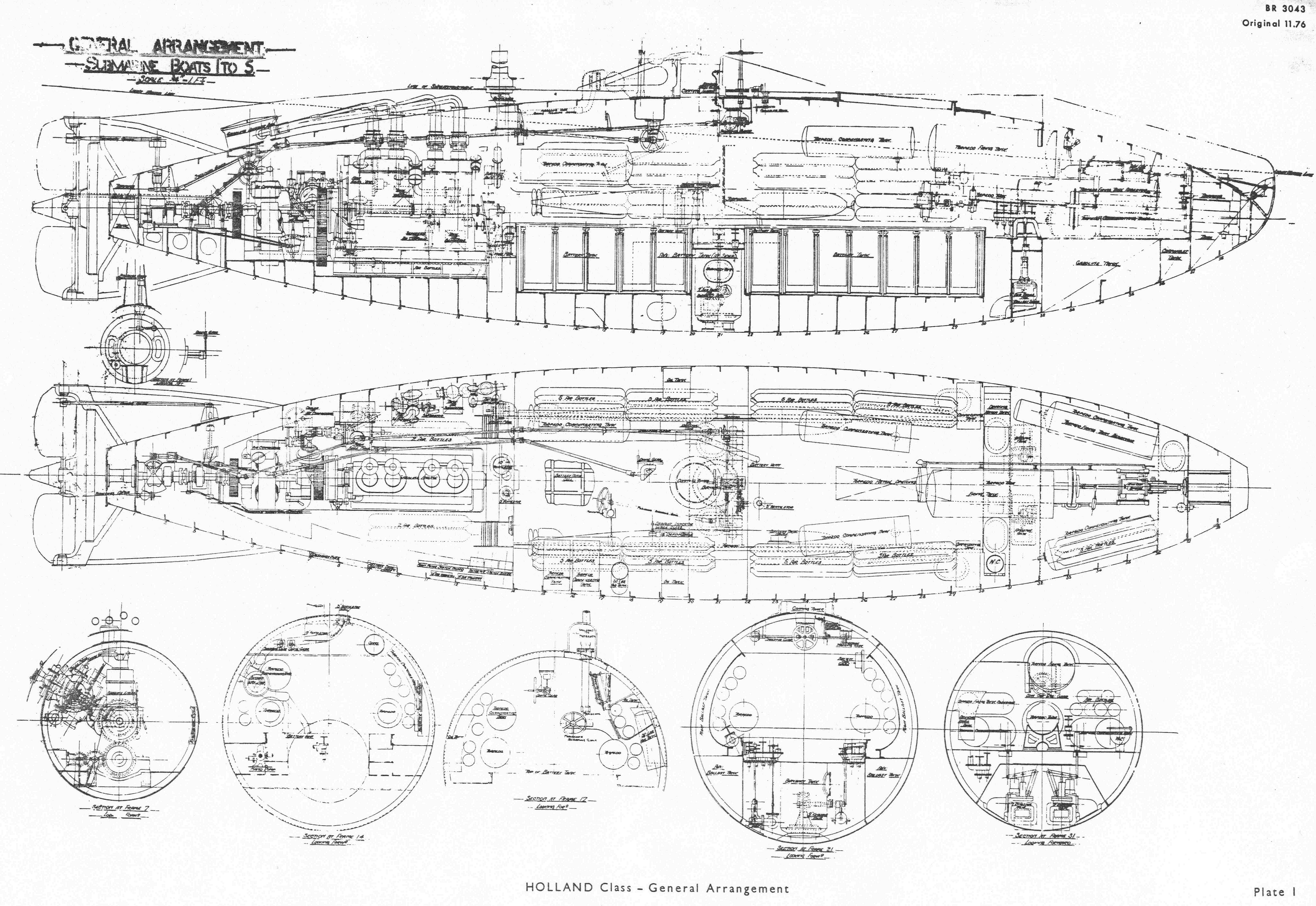
4. A single bow tube was fitted in the Holland Class with the axis slightly bow down so that the lip of the tube was about 2ft below the LWL. There was some doubt whether this was a 14-inch or 18-inch tube since Vickers originally quoted 14-inch and so did DNC probably quoting Vickers. However later on both quoted 18-inch. As specified five short or three long torpedoes were to be carried, one in the tube and the others on trolleys on the battery tank covers. Actually only the three long torpedoes were used with one trolley, the spares being stowed one port and one starboard amidships. The length of the torpedo was about 16½ft. There is good evidence to suggest that on completion or at least soon afterwards only one spare torpedo could be carried or even no spare at all, because of weight restrictions.
The bow cap was right in the bows and opened upwards. See Plate 1 : . It was operated by a bow cap engine sited on top of the torpedo tube and as far forward as it could be placed.
5. Particulars of the torpedo and tube are:
- Weight of torpedo-0.6 tons
- Displacement of torpedo-0.578 tons
- Negative buoyancy of torpedo-0.022 tons
- Torpedo and water in tube-0.89 tons
- Therefore capacity of tube-0.868 tons
Therefore WRT water required was 0.29 tons, AIV water 0.022 tons and the total capacity of the WRT and overflow tank 0.868 tons for firing one torpedo and draining the tube. After firing three torpedoes and keeping the tube full of water these figures become for AIV water 0.066 tons and for the WRT and overflow tanks a total of 1.446 tons.
6. A schematic arrangement of the tanks associated with firing the torpedoes is shown in Fig 27.1 and their actual positions in Plate 1. The drain or compensating tank (the WRT tank) had a capacity of 0.34 tons. It is assumed that the two small compensating tanks, the total capacity of which is given as 0.2 tons, were to take water equivalent to the negative buoyancy of the torpedo. For convenience these tanks are called AIV tanks although of course there was no actual AIV gear at that time. When fitted with a dummy head the torpedo had a negative buoyancy of 0.054 tons and hence the size of these tanks. The six larger torpedo compensating tanks, of approx 0.25 ton each, were so spaced to correct trim when spare torpedoes were brought forward for loading into the tube by blowing water from the forward to the after tanks.
Drains led from the forward and after ends of the torpedo tube through a valve manifold to the WRT tank, which was connected direct to the port and starboard compensating tanks (AIV). After firing a torpedo it appears that water was blown, by air from the auxiliary 50lb/in2 service, from the tube to the WRT tank and a certain quantity from the WRT tank to the AIV tanks. This left approximately 0.5 tons of water in the tube and it is assumed that this was blown into the forward port and starboard torpedo compensating tanks. The latter were emptied into the after tanks as the first spare torpedo was brought forward into the tube and correspondingly for the second spare.
A large firing tank tested to 95lb/in² was fitted over the after end of the tube with a torpedo firing tank reservoir nearby.
7. A 6ft x 1ft 7in. hatch for loading torpedoes was sited on a shallow coaming on the hull just aft of the tube. The torpedoes would have been taken inboard tail first from forward to aft. There is no suggestion that a torpedo loading derrick was carried so outside help was needed,
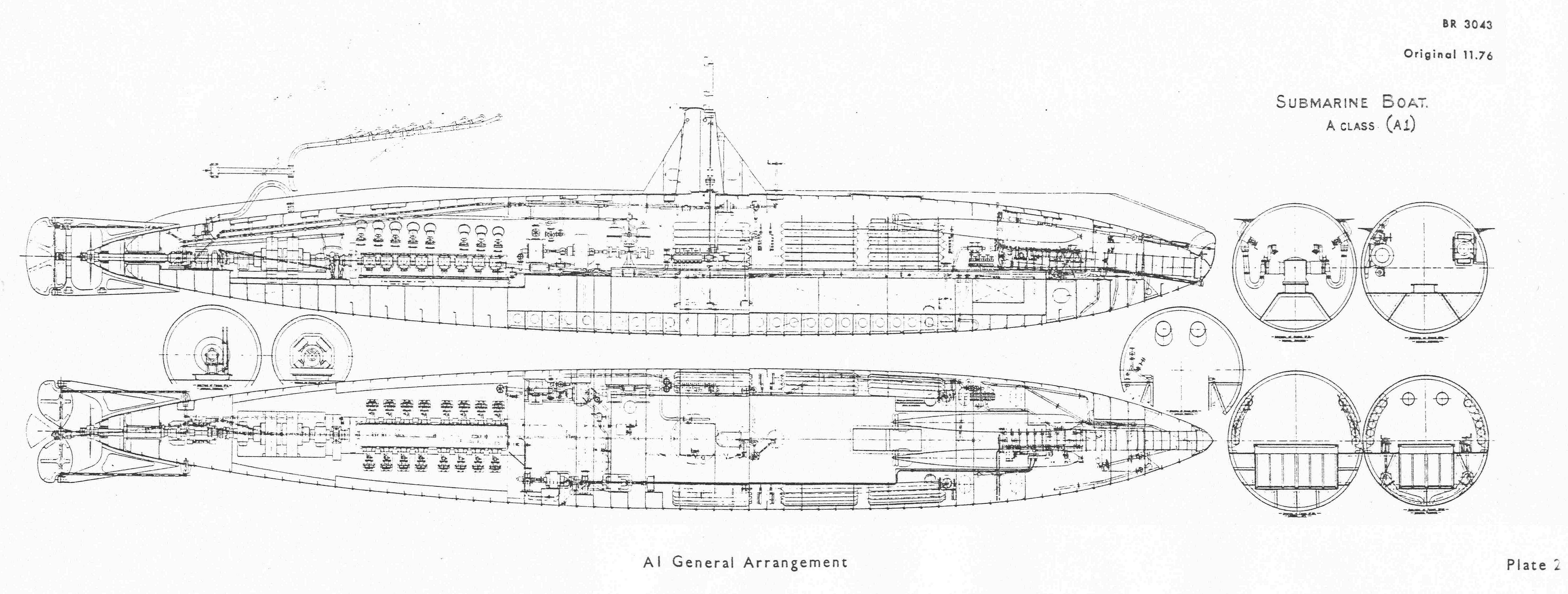
8. A similar arrangement of single 18-inch tube angled about 3 bow down was fitted at the extreme forward end in A1. The bow cap was hand operated through a screwed shaft by a handwheel at the rear end of the tube. The cap opened upwards as in the Holland boats. A securing clip at the bottom of the bow cap to keep it closed was operated by shafting from inboard. See Plate 2.
The two spare torpedoes were slung side by side over the torpedo tube. Torpedo compensating tanks for correcting change in trim when loading spare torpedoes as in the Hollands were not now fitted and were not really necessary. Any small compensation needed for this purpose could be done using other tanks. There was a well under the tube which was probably used for AIV water.
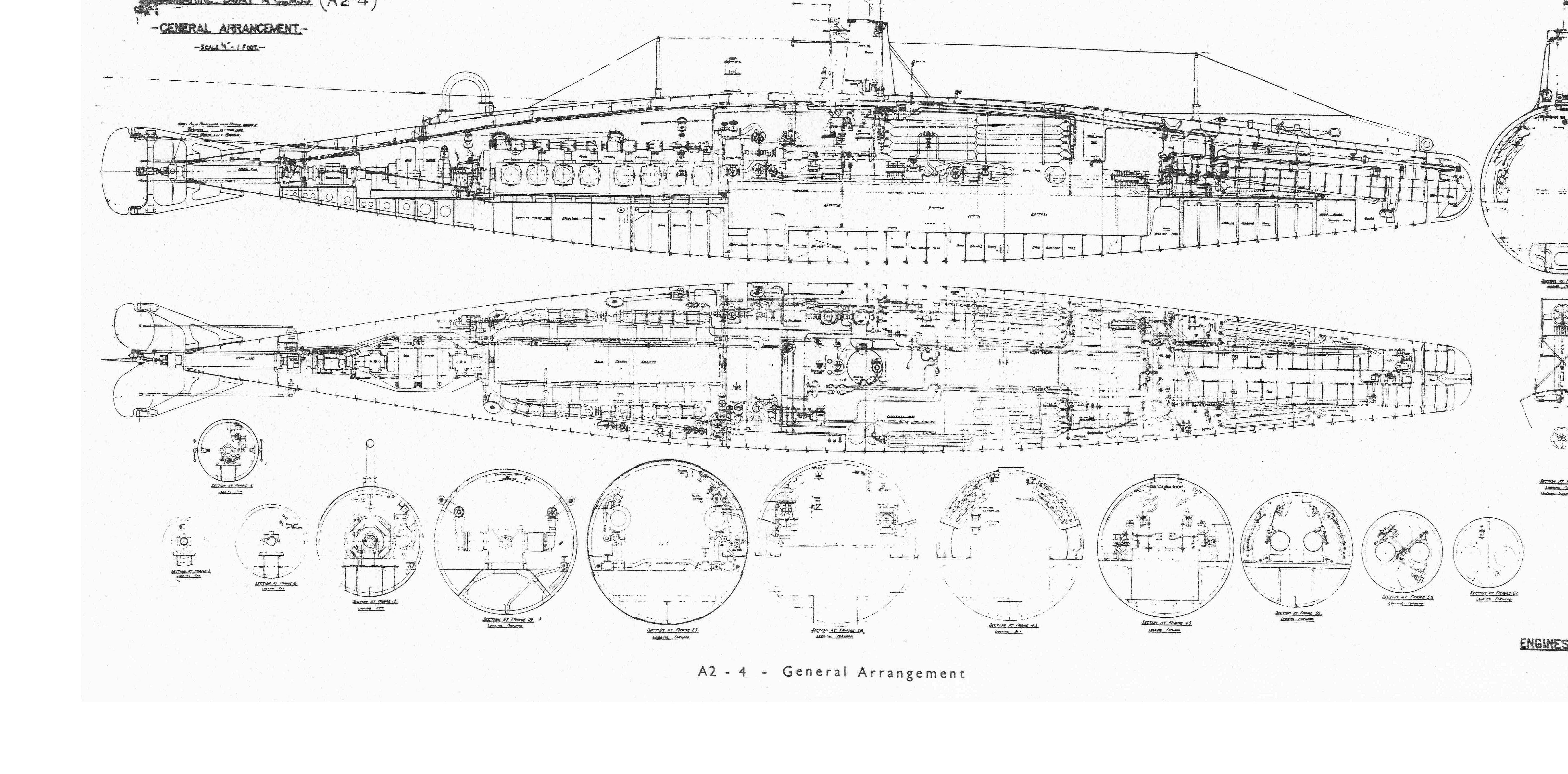
9. In A2-13 it was decided to increase the torpedo armament to two 18-inch tubes fitted side by side again inclined 3° bows down with a distance between centres of 31in. It had been hoped to improve the speed in these boats by changing the form but any gain was nullified by the bluffer bow needed to fit the two tubes. However, by the change in form the additional armament was carried on approximately the same displacement. The tubes were lengthened by about 6ft.
The forward end of the vessel carrying the fore end of the tubes was a 1in thick steel casting weighing 18cwt. The bow caps were in conical shaped steel castings which were hinged upwards by hand. Fairing plates were attached to the outside of the bow caps which moved with the caps and faired in the openings in the bow plating when the bow caps were closed. A handwheel at the rear end of each tube turned 5in shafting with a worm on the end which engaged a quadrant on the bow cap hinge spindle. The locking gear fitted in A1 was deleted. See Plate 3.
Two spare torpedoes were supposed to be carried in A2-13 but within a few years of completion the general rule was not to carry the spares; if they were on board the gasoline had to be reduced to compensate the weight. This restriction also applied to A1.
10. WRT tanks are named for the first time and one tank fitted for each tube with a capacity of just under 0.5 ton each. No torpedo compensating tanks are mentioned and if ever fitted were later removed. Neither is an overflow tank from the WRT tank but there was a large bilge under the tubes which could be used for this purpose and it could also be used for AIV water.
Firing tanks became built-in structures. A2-4 had four tanks with a total capacity of 76ft4fitted at the side and above the level of the battery tank. In A 5-13 this was reduced to two tanks one under the tubes forward and the other on the port side abreast the torpedo hatch with a total capacity of 82ft4.
A portable crane for loading torpedoes was provided in A5-13 and possibly in the earlier A boats. It is unlikely to have been fitted retrospectively in the Hollands. It became a standard fitting in the boats that followed.
11. The same arrangement of tubes was fitted in the B Class and C Class. Although no statement has been seen that spare torpedoes could not be carried the stability was getting so low and there were restrictions on the use of main ballast and gasoline within a year or so of completion that it can be assumed that spare torpedoes were not normally carried. A statement of weights for C21-30 prepared by Vickers during building mentions that 'spare torpedoes (2 in No) are considered in the weights in view of some being carried under war conditions. No provision is made by contractors for their stowage in the boat.'
The tank arrangements were similar to those in the A Class except that in C21 onwards the two firing tanks of nearly 3 tons capacity were fitted forward in the superstructure over the tubes. There were specially built tanks and must have had a beneficially effect on seaworthiness.
In the C Class torpedo trolley rails were fitted overhead from the torpedo hatch to the rear ends of the tubes. These rails were probably fitted also in the B Class.
12. The D Class had two 18-inch bow tubes one above the other and an 18-inch stem tube was fitted for the first time. A spare torpedo was carried for each tube. The tubes were horizontal and not angled downwards as in the previous boats. Watts states that 'the vertical arrangement of the bow tubes enabled the resistance to propulsion to be somewhat reduced from the C Class with two horizontal tubes. The stem tube was an experiment rendered possible by the increased size and altered shape of the vessel compared with the C Class '. By the latter he means the flattened stem with twin screws.
Points of interest in the class are:
- The two bow caps were operated together by a handwheel at the rear end of the tubes through a single rod and gearing. The cap of the upper tube opened downwards and that of the lower tube upwards. The after tube cap opened upwards usingthe same principle as in the C Class.
- The torpedo trolley rails mentioned in Paragraph 11in the C Class were replaced by a fixed loading tray just aft of the tube and a hinged loading tray aft of the fixed one. Both trays were used for loading the lower tube. The hinged tray could be hinged up for loading the upper tube.
- Torpedo crane sockets were provided at the forward and after torpedo hatches for using the one portable crane.
- The two firing tanks fitted in the superstructure right forward in the C Class were moved to just forward of the bridge, undoubtedly because of the congestion in the bows. A third firing tank was fitted aft in the superstructure for the after tube. The position of these tanks varied in different vessels of the class and in some cases are actually found in the bridge structure.
Compensating tanks were fitted forward under the tubes in addition to the normal one WRT tank per tube. No separate AIV tank was provided. This system of tanks remained the general practice for many years.
13. Watts states that 'a demand for broadside tubes and a decision not to accept any form of discharging frame, such as the French used, outside the boat and therefore inaccessible in the submerged condition, had always existed in our submarine service and became more pronounced as the boats increased in size'. As far back as 1908 whilst the D Class was being developed a fear seems to have arisen that the increased size of submarines coupled with increased speed submerged made end-on attack at short range difficult. This is explained in more detail in Chapter 4 Paragraph 14
It appears that experiments were made which showed that it was possible to fire torpedoes from a submerged beam tube at moderate speed without the bar (frame) and a broadside tube was designed which could be carried in a submarine with 2½ ft more beam than the D boats.
14. The E Class had been designed late in 1910 and E1 was laid down in February 1911. The only vessel with increased length and submerged speed which could be tried and might allay the fears about the difficulty of end-on attack with these bigger boats was D1 which had completed in September 1909. She was in a sense an experimental vessel and would have had a large trial programme to complete on the working of the submarine itself. The introduction of beam tubes would undoubtedly complicate design.
The E Class was however designed with broadside tubes amidships. Although at the time the complete omission of bow tubes was given serious consideration E1-8 were fitted with one bow, two broadside and one stem 18-inch torpedo tubes with a spare torpedo for each tube.
By the end of 1911 a number of the D Class were at sea. Whether it was that actual trials in these boats had shown the anticipated difficulty in short range end-on attack had been exaggerated or whether it was from a reappraisal of the problem, from E9, laid down in June 1912, onwards the bow was lengthened so that two 18-inch tubes could be fitted.
15. A relevant point arose at the time. Submarine officers were trained to attack at short range and high speed and short range torpedoes had been considered therefore most suitable for our tactics. About 1911 the want of a long range torpedo for 'browning' when the submarine could not get into close range had become apparent and long range heater torpedoes were developed for bow discharge. They were supplied to the D and E Class and later overseas vessels. The other torpedoes were 18-inch cold. By April 1914 special 18-inch heater torpedoes, the Mark VIII, were being manufactured for the S Class, V Class, W Class and F Class coastal submarines and the broadside tubes of the Nautilus and Swordfish. They had a speed of 41 knots and a range of 1500 yards.
On service the beam. torpedoes proved to be very good for submerged running and the success of the broadside tube exceeded expectations. Apparently the Germans intended to fit broadside tubes in some of their larger submarines but according to reports from German sources they failed to get a successful tube and the matter was dropped.
16. To accommodate the beam tubes in the E Class the pressure hull in the vicinity of the tubes had to be extended out to the saddle tank plating as shown in Plate 15. The tubes were split and the top half opened by worm and quadrants operated by two handwheels to each tube. The torpedo loading hatch was at the fore end of the engine room. This hatch, and also the torpedo hatch forward, was opened and shut mechanically by a handwheel through shafting, worm, rack and bevel wheels. The torpedo was passed through a WT door in the engine room bulkhead on to an overhead rail and lowered into a beam tube when in position. The spare torpedoes were slung athwartships one over each tube. The caps of the tubes were operated by gearing from positions alongside the lip ends of the tubes.
17. Two internal main WT bulkheads were fitted in E1-8, one forward to form a forward torpedo room and the other at the forward end of the engine room. They were therefore the first submarines to have a certain amount of watertight subdivision. However the distance between the rear end of the bow tube and the bulkhead was such that the tail of the torpedo had to project through the bulkhead WT door when loading the torpedo into the tube. The spare torpedo was stowed, without its warhead, at the starboard side of the tube on rails to facilitate drawing it aft for loading. The warhead was stowed separately in the torpedo room. The bow tube and bow cap opening was as fitted in the C Class.
The stem tube was also of the C Class type. Torpedoes were loaded through the engine room hatch and brought aft on an overhead rail. The spare torpedo was stowed abreast the tube on the port side.
Firing tanks were fitted in the superstructure over each set of tubes.
18. In E9 onwards the bow was lengthened by 3ft to allow two tubes to be fitted side by side. This gave better protection to the bow caps. Bow shutters were fitted for the first time. The bulkhead at the after end of the torpedo room was moved 2ft further aft so that the tail of the torpedo did not project through the WT door when loading the tube. The two spares were stowed in the torpedo room on the port side aft of the tubes still without warheads. The two warheads were stowed on the starboard side of the torpedo room flat.
The arrangements of the amidship and stem tubes remained as in E1-8 although it is stated that the facilities for working torpedoes in both positions were improved.
In E9 or soon after the firing tanks were brought from the superstructure inboard and were built as part of the structure and tested to 95lb/in2. There was one tank for each tube.
In E24, E34, E41, E45, E46 and E51 built as minelayers the beam torpedo tubes were not fitted.
19. S1 was building at the same time as the early boats of the E Class, in fact S1 completed in August 1914 the same month as E10. An Italian design, the S Class had two 18-inch bow tubes fitted side by side low in the vessel and angled bow down so that the lip ends of the tubes were less than 1ft from the underside of the keel in a form of bulbous bow. The fore ends of the tubes were cut at an angle of about 45° and covered by bow caps which hinged outwards away from the middle line. These caps when closed formed an angled face to the bulbous bow. Two spare torpedoes were carried.
The rear doors of the tubes were of a quick opening and closing type. See Fig 27.2. 'A small movement of a lever actuated a toothed ring which impressed at the same time similar projections on the door. It can be described as a combination of a gun breech and a bayonet joint. A very strong interlocking gear prevented the doors being opened when the bow caps were open. '
The torpedo tubes were surrounded by tanks; one called the torpedo compensating tank was obviously the WRT and two buoyancy tanks (air) are assumed to be the firing tanks. The tops of these tanks formed a walking space with spare torpedo compensating tanks at the sides. 3½in sea valves were fitted port and starboard sides at the rear end of the tubes with valves chests for flooding the tubes and compensating tanks direct from the sea. Main line suctions were fitted to the tubes and all tanks including the buoyancy tanks.
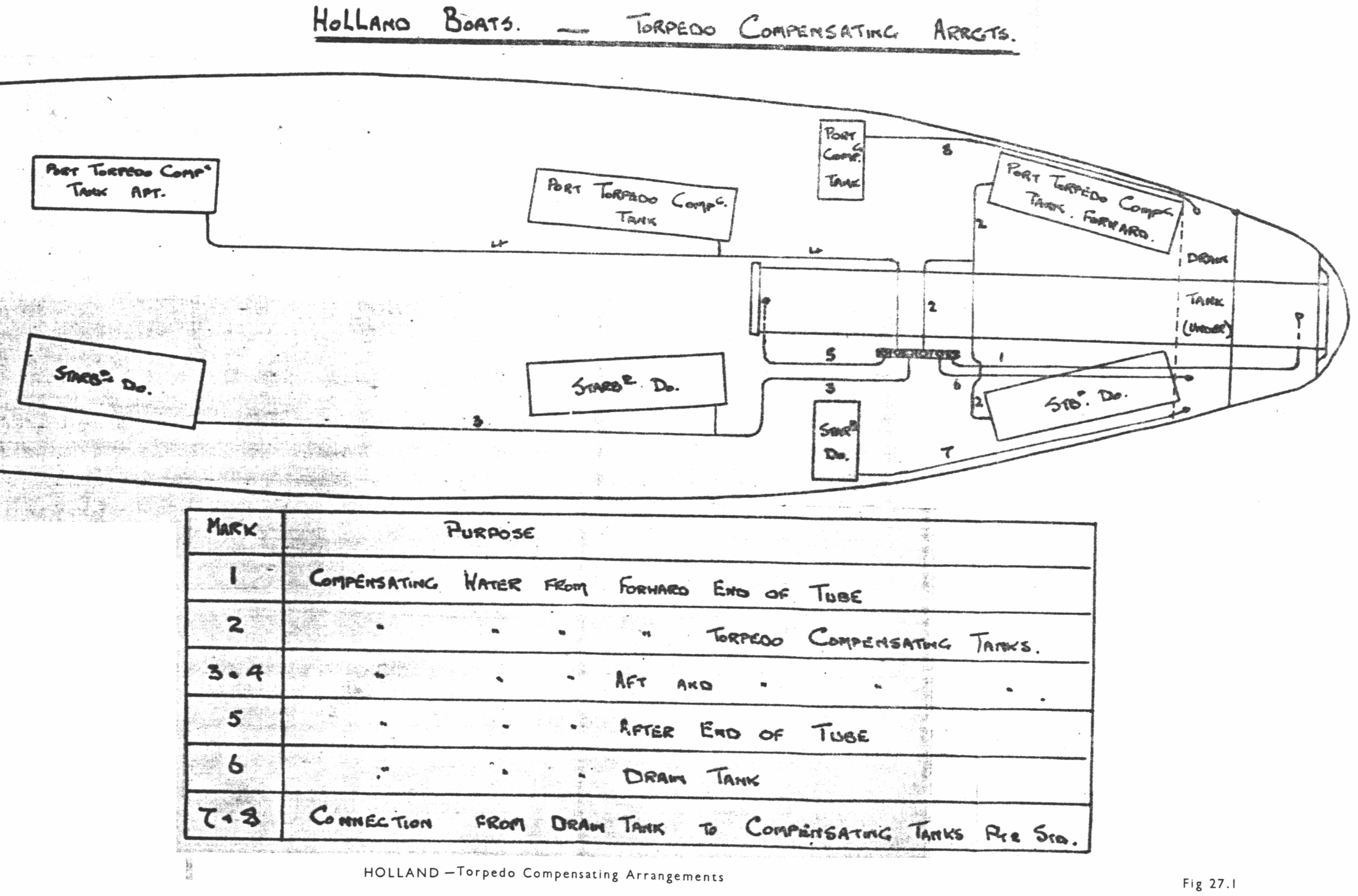
Fig 27.1
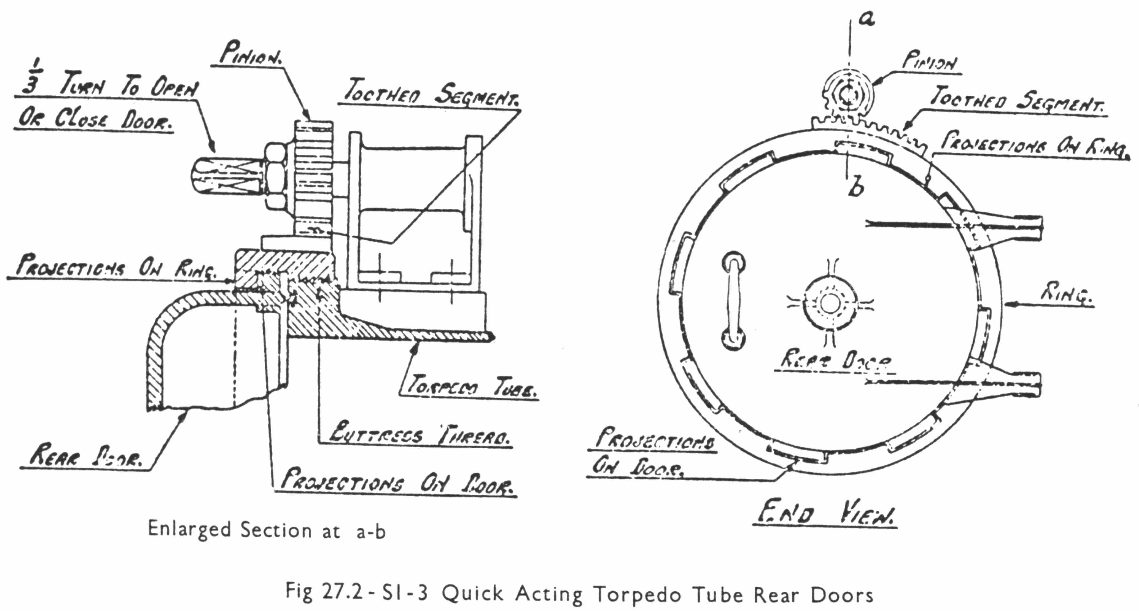
Fig 27.2
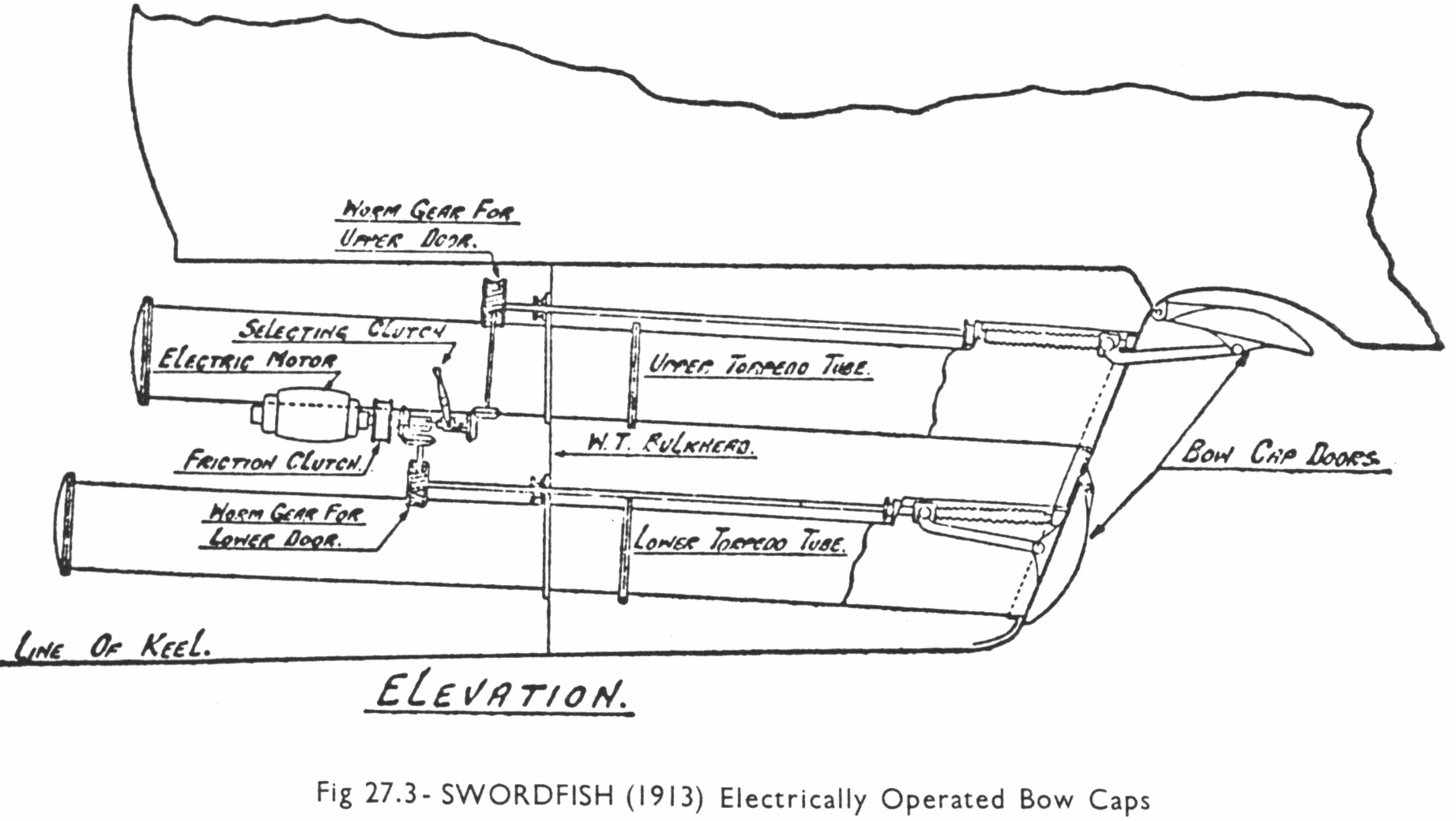
Fig 27.3

Fig 27.4
The torpedo hatch was shaped on the lines of the modern torpedo hatch which suggests that some sort of loading rails might have been provided. See Fig 27.4.
20. The V Class had two bow 18-inch tubes very low in the vessel rather on the lines of the S Class. See Plate 17. The bow caps hinged upwards. Two spare torpedoes without warheads were stowed on the starboard side of the torpedo room one above the other and the warheads near by on the flat.
A cylindrical firing reservoir was sited on the port side of the torpedo room. The torpedo hatch was mechanically operated as in the E Class.
21. As designed Nautilus had one bow 21-inch torpedo tube, four beam 18-inch tubes and two stem 18-inch tubes and this is the arrangement shown on Plate 19. However, experience early in the war showed the greater efficiency of attack with multiple bow tubes and the one 21-inch tube was replaced by two 18-inch tubes. Eight spare torpedoes were carried, one for each tube. The only points of change are that the spare torpedoes were stowed with the warheads attached and that the firing tanks were actual spaces in the double-hull.
22. In the French designed W Class, W1 and W2 were supposed to have two 18-inch bow tubes and four 18-inch external tubes in 'frames', which were the French pattern of carriers from which when fired the torpedo was simply detached and proceeded under its own power. The external tubes were deleted from the design of W3 and W4 and it seems reasonable to assume that they were not fitted or were removed from W1 and W2. The F Class was based on the V Class with the addition of a stem 18-inch tube.
23. It can be said that Swordfish was the first British submarine to be designed and to start building to carry 21-inch torpedoes but she was not the first at sea, the G Class taking that honour. Two 21-inch bow tubes were fitted one above the other in the lower half of the hull with the upper tube about 2ft further forward than the lower tube. Both tubes were angled bow down. Four 18-inch beam tubes were also fitted.
On account of their size, Scotts proposed that the bow caps should be operated by power which was a departure from previous practice. They worked out designs and approval was given for electrically operating the bow caps as shown schematically in Fig 27.3. It is understood the arrangements as fitted gave entire satisfaction.
Scotts also fitted a new type of torpedo hatch forward which was used not only for the passage of torpedoes but also for ammunition. See Fig 27.4.
24. The original design of the G Class included a single 21-inch tube forward but for the reason mentioned in Paragraph 21 for Nautilus two 18-inch bow tubes were fitted instead. In addition they had two 18-inch beam tubes amidships and one 21-inch tube aft with a total of ten spare torpedoes. Rightly therefore theG Class was the beginning of the 21-inch torpedo in RN submarines since they were all at sea a considerable time before Swordfish was completed.
25. The J Class had four bow and two broadside 18-inch tubes with a spare torpedo for each tube. This was the first British design with four bow tubes. The boats were very fine in the bows, as was very necessary to obtain the high speed of 19.5 knots required, and there was little room between the tubes for the rods and mechanisms required for the independent operation of the bow caps and shutters which had been the practice in the earlier E Class and G Class. A mechanism was therefore designed to open and close the cap and shutter in one operation. The completed gear was quite successful and was fitted in all later classes.
26. Although four 21-inch bow tubes were included in the original design of the K Class to adopt them would apparently have meant an entirely new design of tube although two 21-inch bow tubes were fitted in the Swordfish which was soon to be completed. Details of a four 18-inch bow tube arrangement had been worked out for the J Class. Broadside 18-inch tubes offered no difficulty. For quick building it was necessary therefore to adopt 18-inch tubes throughout. The K Class had four bow and four broadside tubes and carried eight spares with warheads attached which now had become standard practice. In the final design twin 18-inch deck tubes to be used on the surface at night were included but they were subsequently removed where fitted.
After the war there were complaints that the bow shutter gear was weak and unable to withstand heavy bow seas. From the trouble experienced with bow shutters later on in slower boats the defects in the K Class with power for a speed of 24 knots are not surprising. Another disadvantage mentioned when considering new designs was that they had only 18-inch tubes.
27. Points of interest in this class are:
- Specially built cylindrical firing tanks, later columns, now seem to be well established, one tank for each tube sited near to the tube. Looking back, the original Hollands had a specially built firing tank which was dropped in later classes until reintroduced in the V Class.
- A separate WRT tank was supplied for each tube, eight in all small tanks mostly less than 1.0 ton capacity, which seems to have been an unnecessary complication. This was corrected in K26 in which the forward six tubes used one common WRT tank.
- Although Fig 8.1 shows the amidship spare torpedoes stowed athwartships it is understood that the normal position was fore and aft, two starboard and two port over the tubes. The torpedo hatch was on the starboard side in the broadside tube space and an overhead rail ran from this space to the fore end for transporting torpedoes to the bow tubes.
28. In the M Class, M1-2 had four 18-inch bow tubes and M3-4 four 21-inch bow tubes. The latter two boats were increased in length by 10ft over the former to allow the larger tubes to be carried. Neither broadside nor stern tubes were fitted primarily because the 12-inch gun had been installed to supplement torpedo attack against high-speed surface vessels.
29. The American H1-20 Class was fitted with four 18-inch bow tubes. This was changed in the H21 Class to four 21-inch tubes but they could carry only two spare torpedoes. This change in size of tubes alone was responsible for an increase in length of the boat by about 20ft and in surface displacement of 70 tons coupled with a reduction in fuel and surface endurance.
30. The original design of the R Class had four 18-inch bow tubes and a submerged speed of 13.5 knots. This was later changed to six bow 18-inch tubes and a submerged speed of 15 knots all at the expense of surface speed. Only one spare torpedo was included in the design stage but this does not appear to have been carried in peace time. The war complement was stated in later years to have been six spares. Space in the fore end was very cramped and there was no torpedo room as such. Torpedoes were embarked through the torpedo hatch in the PO's mess tail first, drawn aft and then transported forward through bulkhead doors directly into the tubes. Any spares would have been stowed in the PO's mess and as far as can be judged at the expense of the PO's bunks. The R boats were the first RN submarines to have six bow tubes.
31. The L Class was really the first conventional type of overseas submarine designed since the E boats and was based on that class incorporating the lessons learned up to the end of 1915. L1-8 had four 18-inch bow tubes and two broadside 18-inch tubes and carried a spare torpedo for each bow tube, but no spares for amidships. In L9 onwards 21-inch tubes were fitted in lieu of the 18-inch bow tubes and an additional main WT bulkhead fitted a few feet aft of the rear end of the tubes to separate the tube compartment from the torpedo room. This started the modern practice in all later submarines including the H Class and K26. The length overall had to be increased by 7ft 6in to accommodate the 21-inch tubes and the additional bulkhead. In those boats fitted as minelayers the broadside tubes were omitted.
The L Class had most of the items of progress mentioned so far with bow shutters and bow caps operated together, a torpedo derrick which stowed in the superstructure and a modem design of torpedo hatch.
32. The L50L50 Class had six 21-inch bow tubes with six spare torpedoes but no beam or stem tubes.
K26 had six 21-inch bow tubes and four 18-inch beam tubes. Later it was approved to remove the beam tubes and this was done about 1929.
X1 reverted to the L50L50 Class torpedo armament of six 21-inch bow tubes without beam or stem tubes.
33. After the E Class and G Class stem tubes were not fitted and this practice continued up to and including X1. They were reintroduced in Oberon mainly on the score that 'after tubes would be of use whilst attacking a fleet or convoy screened by A/S vessels. '
When the torpedo armament for the Odin was being discussed the Commanding Officer of Oberon (then building) proposed that stem tubes should not be fitted;
- To save space urgently required for store rooms and living space.
- To allow the stem to be fined off to increase speed.
- Less material to maintain for an already over-burdened crew.
There was considerable agreement with this proposal on the grounds that 'two tubes on one bearing are quite ineffective against a modem ship and at least six tubes are required. ' RA(S) however did not agree.
During discussions on the Staff Requirements the provision of stem tubes had been in the balance. They 'were desirable but they should not be included if an extra two knots speed could be obtained by their omission. Model experiments at the Admiralty Experiment Works Haslar showed no gain in speed with the same power if the stem tubes were omitted and so the design proceeded with them.
34. Oberon, Oxley and Otway had six 21-inch bow tubes and two 21-inch stem tubes with a spare torpedo for each tube both forward and aft.
The Odin Class, Parthian Class and Rainbow Class had six 21-inch bow tubes with six spare torpedoes and two 21-inch stem tubes without spare torpedoes; first of all Mark 21 IV* torpedoes later changed to Mark VIII-VIII* and in 1930 to Mark IV*S type.
35. In the Odin Class a number of important improvements to the torpedo tubes were to be introduced. They were designed to withstand the diving depth of 500 feet and to be suitable for 'disc' discharge. Quick closing rear doors were designed. Bow shutters were abolished. See Chapter 14 Paragraph 56. It is not known whether all these items were finalised in time to be fitted in the Odin. AIV gear was fitted for the first time.
Originally in Odin one WRT tank for all six tubes forward had an overflow to B auxiliary tank but before completion a torpedo overflow tank (TOT) was introduced. The AIV water went into the bilges since the fitting of AIV gear was not introduced until after the design had been approved and the arrangement of tanks did not permit of an AIV tank being fitted. Without reloads aft a single WRT tank was sufficient but an AIV tank was fitted. Odin was the first submarine to have designated TOT and AIV tanks. About 1935 the policy changed and closed AIV tanks were deleted.
36. In the following Thames Class, Swordfish Class and Porpoise Class the stem tubes were abolished and the torpedo armament consisted of six 21-inch bow tubes with six spare torpedoes.
37. Power loading of torpedoes was first fitted in K26, hydraulic presses and wires being provided for this purpose.
This form is for you to comment on, or add additional information to this page. Any questions will be deleted. If you wish to ask a question contact the Branch or the Webmaster using the Contact Us page or ask your question on our Facebook Page


