Chapter 21: Rudder and Steering Gear
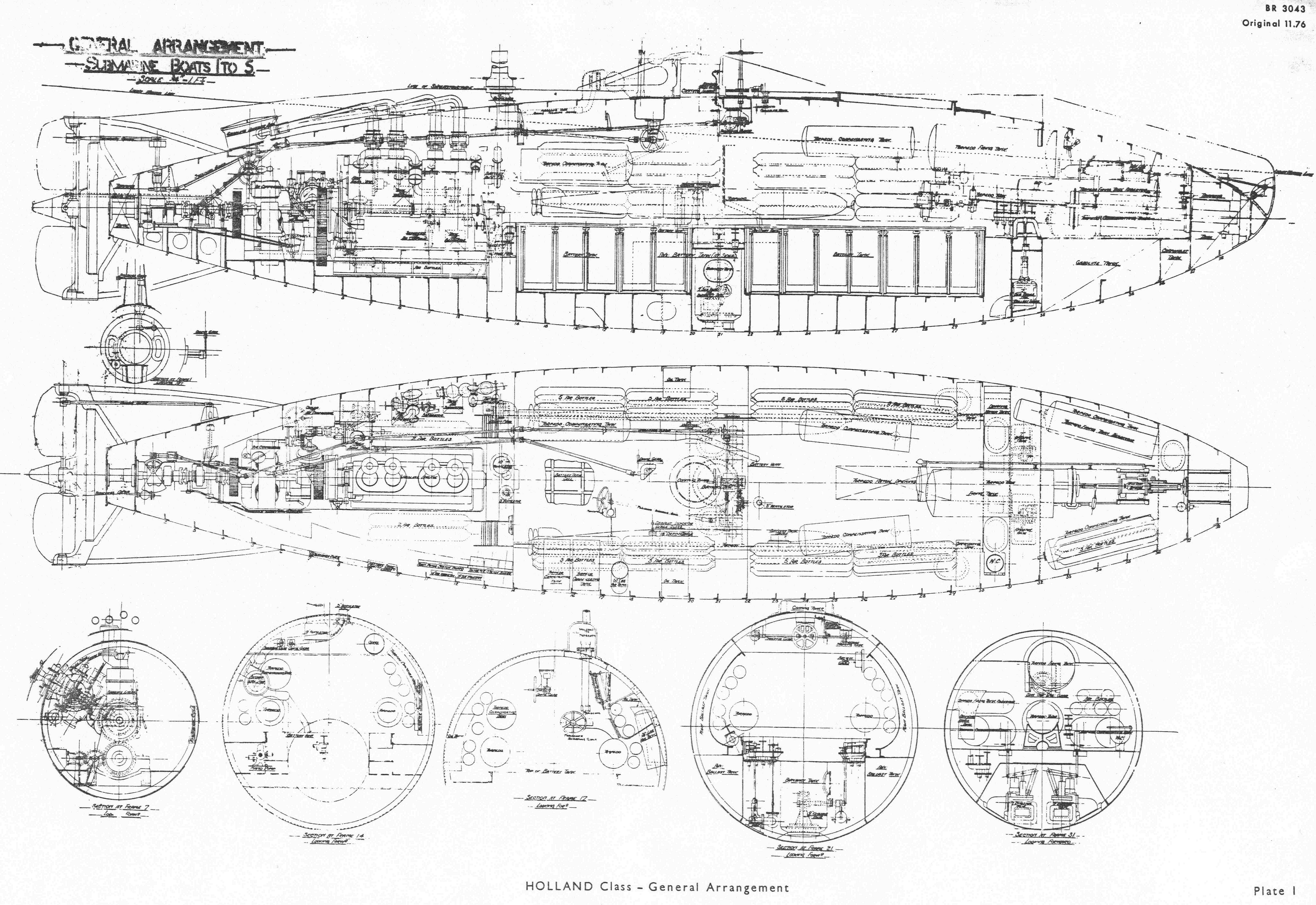
1. The rudder post in the Holland boats was about 2ft 6in aft of the pressure hull and was supported at the top and bottom, and at mid height in a framework from the main hull. The rudder was in halves spaced equally above and below the main axis of the boat. of total area 12.66ft2, made of double 10lb. plate and moved 35° to port and starboard.
2. Originally operated by a compressed air reciprocating piston engine attached directly to the rudder this system, as for the hydroplanes, was found to be unsatisfactory and was replaced before the boats were completed by rods and gearing hand operated from the control room. The arrangement is shown in detail in Plate 1. From the steering pedestal the control shafting ran as far aft as possible to a rack and pinion gear on a shaft which passed vertically outboard and from which a lever operated a rod connected on to and near the top of the rudder. It is stated that originally in Holland No 1 and No 2 the connections from the rudder to the pinion shaft were of ¼in. wire rope and there must have been two of them. This was later changed to the one rod.
3 The upper steering wheel was sited just forward of the conning tower and the coxswain sat on the edge of the conning tower when steering. This wheel and the outboard shafting was portable. The steering wheel in the control room was directly under the conning tower and over 5ft above the deck. A conning tower stand was fixed to the deck an could be adjusted in height so that the helmsman could stand on it and see through the scuttles in the sides of the conning tower when steering. This was for use when weather conditions on the surface made the upper steering position untenable. By means of bevel wheels and shafting a third steering wheel was available at the periscope and this wheel and shafting could hinge up and stow overhead when not in use. Draught indicator gauge glasses were placed in the control room near the steering position and also in the conning tower.
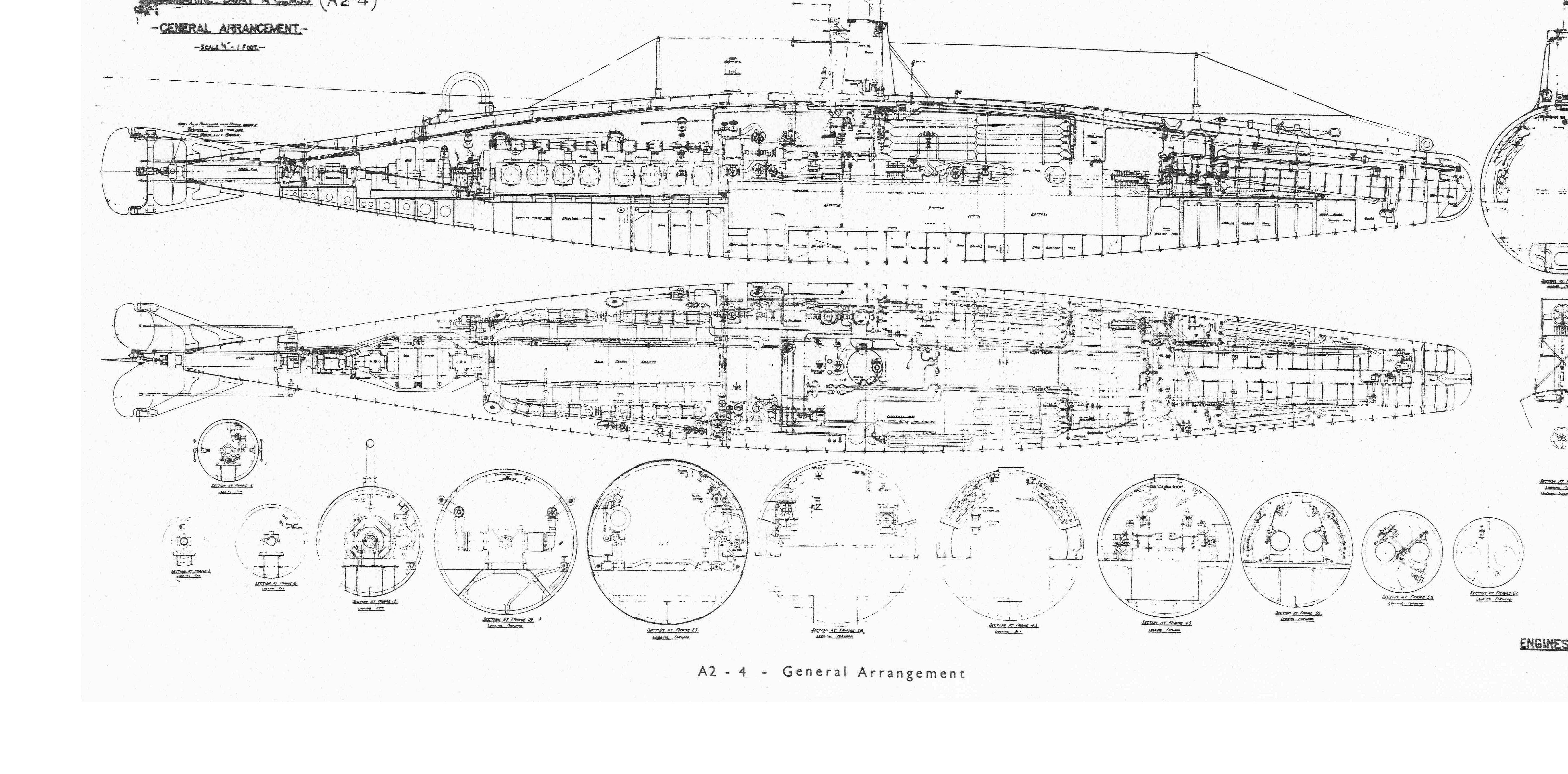
4. In the A Class, a single rudder of 17.75ft2 area was supported at the top and bottom only. The control shafting passed through a gland in the pressure hull with a worm and worm wheel quadrant outboard, the latter being attached to the rudder near the upper pintle. The gearing was of course in the sea but could be examined if necessary on the surface with the boat trimmed bow down.
The upper steering wheel was still just forward of the conning tower until the introduction of larger conning towers and bridges in 1904/05 when the steering control was improved. The arrangements in A2 are shown in Plate 3. The upper steering wheel was sited on the bridge and shafting led from it through the pressure hull to a lower steering wheel and then aft. The steering wheel and shafting outside the pressure hull was portable and removed for diving. The lower steering position had been at the fore end of the control room but was now moved further aft near to the diving wheel. The third steering wheel at the periscope was deleted. A lead of shafting from the steering control shafting operate a rudder indicator fitted in the conning tower.
A point of interest in A1 is that she was fitted with a reversing propeller. The reversing gear was operated by a ratchet lever sited near a propeller reversing block on the main shaft at the forward end of the stem tube. Similar reversing propellers were fitted in A2-4 but all were removed and conventional propellers fitted before the boats left Barrow.

A1
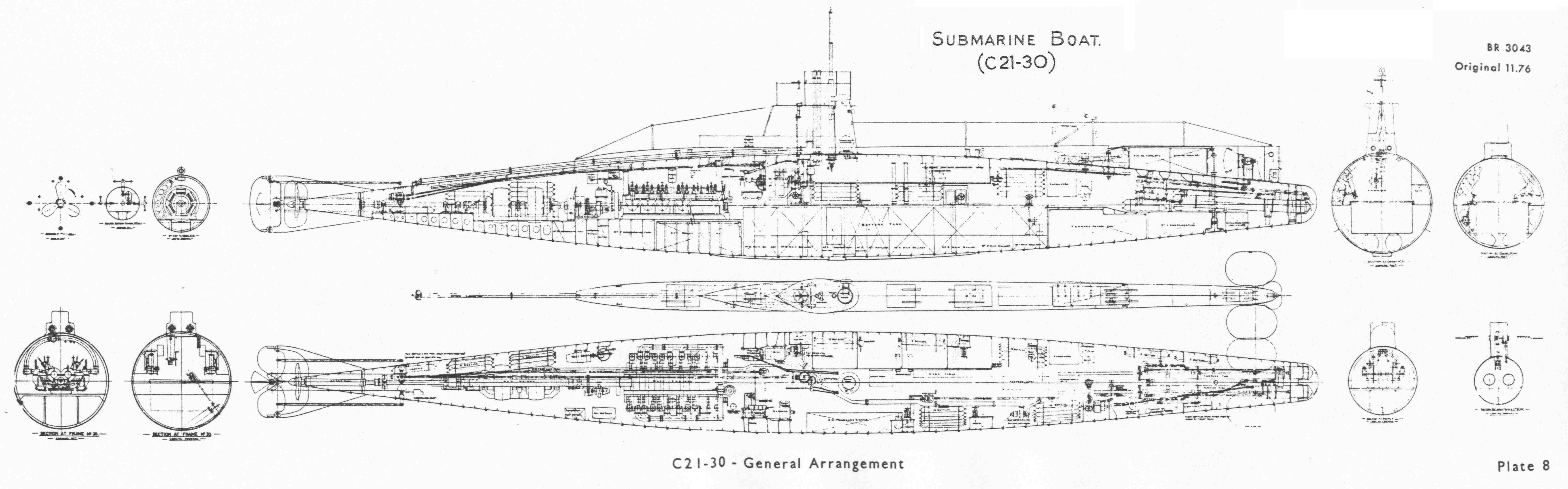
5. Similar arrangements to those in the A Class were fitted in the B Class and C Class except for the following major changes:
- In B11 onwards a steering motor was fitted at the control room pedestal of 2ghp in B11 and 2hp in the C Class. The rudder could therefore be operated through the control shafting from the control room in power or by hand. Similar arrangements were undoubtedly fitted retrospectively in some of the earlier boats.
- The lower steering wheel was in the conning tower in the B Class presumably to allow the helmsman to be alongside the periscope officer when closed up submerged. In the C Class the lower steering position returned to the control room.
- From about C19 onwards, the control rod gearing aft was brought inboard as in the Holland boats but of improved form with port and starboard control shafting outboard to the rudder; see Plate 8.
- The rudder area was increased to 25ft².
6. The larger twin screw D Class brought in a different shape of stem and the introduction of a balanced cruiser type rudder with a pintle bearing on the stem fin half way up the rudder in D1 and at the bottom of the rudder in D2-8. In D3-8 the rudder stock was inclined forward and the only reason that can be suggested for this is to decrease the 'bow rise on turning' which had affected earlier submarines.
An interesting feature is the introduction of an upper rudder on top of the pressure hull aft. The area of the two rudders were practically the same of the order of 30ft each and they were geared to operate in unison by control shafting, bevel wheels and worm and worm wheels rather on the lines of the B Class arrangement with the worm and worm segment outboard on the lower rudder and inaccessible except in dock. See Plate 11.
Steering positions remained as in the C Class with a 2hp motor on the control room pedestal. The upper steering wheel was sited so that it could remain in position and not be removed when diving. Rod gearing was installed for steering telegraphs at both the upper and lower steering positions; first noted in C19.
7. The arrangements in the E boats at first followed the D Class pattern. An upper rudder was fitted but trials in E4 showed that the improved manoeuvring submerged was so marginal as to make the disadvantages attending its use not worthwhile. They were removed from the few boats then fitted. See Chapter 4 Paragraph 21.
The mechanism aft for operating the rudder was entirely revised. The inboard end of the rudder stock was fitted with a tiller arm operated by two rods on a screw gear controlled by shafting from the control room. All the mechanism was now inside the boat and accessible. The pedestal motor was increased to 3hp to take account of the increased rudder area and speed. The rudder area was 38. 9ft² in E1-18 and 40ft² in E19 onwards.
A third steering position in the conning tower was introduced.
8. The E Class arrangements were followed in a number of other classes building at the same time although none appear to have adopted the inclined rudder. The S Class and V Class and Nautilus were in this group and probably the F Class. In Nautilus with a rudder area of 71ft2 a 9hp control motor was fitted. There was also an emergency steering pedestal on the after casing with a 9hp motor inboard. Nautilus had the three steering positions as in the E Class, the smaller boats did not have the conning tower position.
9. For Swordfish, laid down February 1914, Scotts designed and installed hydroelectric steering gear similar to the power operation of the hydroplanes mentioned in Chapter 20. The control motor was moved from the control room steering pedestal to a position aft near the screw-type steering gear and in conjunction with a Williams Janney unit worked the tiller. The motor was operated by shafting from the control room. In the event of motor failure arrangements were incorporated to enable the steering gear to be worked by hand direct from the control room pedestal.
Scotts stated that subsequently the E Class, G Class and K Class were so fitted. This probably referred to E31, E51, G14 and K15 built by Scotts. In the vessels of the E Class and G Class built by Vickers the arrangements mentioned in Paragraph 7 were definitely installed.
10. Some features of the various classes which followed are:-
- G1-13 were as the E Class. Rudder area 38. 3ft2. Control motor 3hp.
- Mechanical transmission was fitted in many of the K Class with a 5hp motor aft. However K17, the last of the class built at Vickers had a Brown's telemotor control system which also incorporated a telemotor control hand gear. The rudder area was 84ft2.
- M1 and M2 also had a Brown's telemotor control system as mentioned above. The rudder area was 67ft².
- The arrangements in the J Class were as in the E Class but with a 10hp control motor. In addition a large handwheel was fitted in the steering flat which enabled four men to operate the rudder by hand.
- The L Class system was as in the H Class with the rudder right aft. Mechanical transmission was to a 5hp motor aft which operated a screw gear, but there must have been external rod gearing to the rudder tiller. Hand gear also fitted. The rudder area was 52. 8ft2 with movement 35° to port and starboard. Steering positions were on the bridge, in the control room and in the conning tower.
- Twin spade rudders were fitted in the R Class for quick manoeuvring. They were side by side 36ft from the stem and 3ft 6in apart with a single centre line guard forward of the rudders. A tiller connected the two rudder heads and was operated by a single shaft from a 5hp motor at the control room pedestal. The rudder movement was 30° to port and starboard
11. Over a period of seventeen years from the ordering of the Holland boats to the end of the war in 1918 the steering gear and rudder arrangements had made progressive development through many different types of submarine generally without major difficulties. From 1920 onwards the rudder was positioned under the hull in association with the stem fin. Telemotor operation was adopted which allowed control shafting from the steering pedestal in the control room to the steering flat to be dispensed with. The odd class out was the Swordfish (1930) in which the control shafting was retained.
Perseus and Proteus were fitted with unbalanced rudders since trials had shown that for submarines an unbalanced rudder gave rather better turning circles on the surface that the normal balanced rudder. Subsequent vessels had unbalanced rudders.
12. In much later submarines than those discussed in previous chapters the steering gear was worked off the main telemotor system, a practice that was also adopted for the hydroplanes as mentioned in Chapter 20. In addition there was only one steering pedestal and that was in the control room; the bridge steering wheel and bridge telegraphs were dispensed with.
This form is for you to comment on, or add additional information to this page. Any questions will be deleted. If you wish to ask a question contact the Branch or the Webmaster using the Contact Us page or ask your question on our Facebook Page

